


richboy2307
Staff
-
Joined
-
Last visited
Everything posted by richboy2307
-
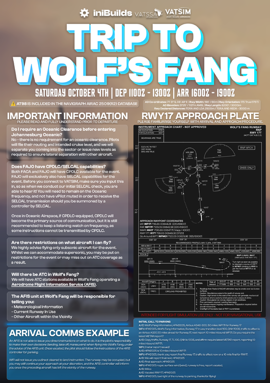
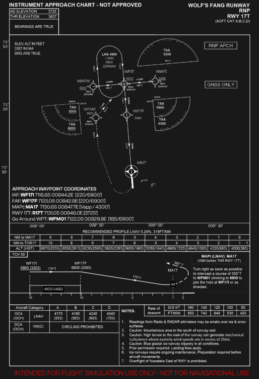
Wolf's Fang Runway IATA: WFR ICAO: AT98 (recognized via Navigraph Navdata / Simbrief only) LID: AT98 AD Co-ordinates: 71° 31′ S, 08° 48′ E (FMS Format: 7131.0S / 00848.0E) AD Elevation: 3725' / 1127m AMSL Rwy Length: 8200' / 3000m Rwy Width: 196' / 60m Rwy Orientation: 175 True (175T) Rwy Declared Distances: TORA AND LDA 2500m / TORA AND ASDA – 3000 m Common Routes (FACT - AT98) You may use any of these below on Simbrief for planning purposes IMSOM UQ36 APKIN UL211F ITLIK 3713S 4112S 4811S 6209S 6808S GEPAB 4018S 5016S 5814S 6412S 6810S 7008S IMSOM UQ36 APKIN UL211F ITLIK 3615S 4014S 4513S 5013S 5513S 6012S 6511S 7010S You may also append the following waypoints from the approach segment for the final part of your flightplan as necessary 711635S0084411E 712133S0084525E 713034S0084741E Suggested Approach Custom Waypoints You may create these custom waypoints in your aircraft FMS for a straight in approach to RWY 17T IAF: WF17I 7116.6S 00844.2E [220/6900'] FAF: WF17F 7123.0S 00842.9E [220/6900'] MAPt: MA17 7130.6S 00847.7E [Vapp / 4300'] RWY 17T: R17T 7131.0S 00848.0E [3725'] Go Around WPT: WFM01 7122.0S 00829.9E [185/6900'] (Click to enlarge images) Note: These are approximate waypoints and will keep you on path but once you have the runway in sight, you should proceed visually.
-
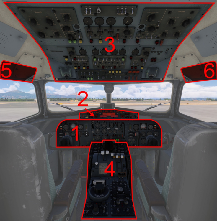
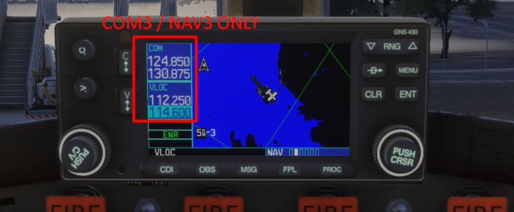
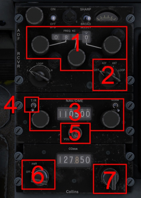
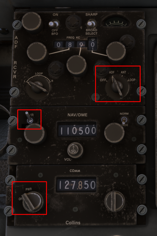
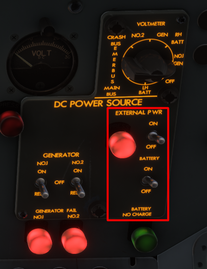
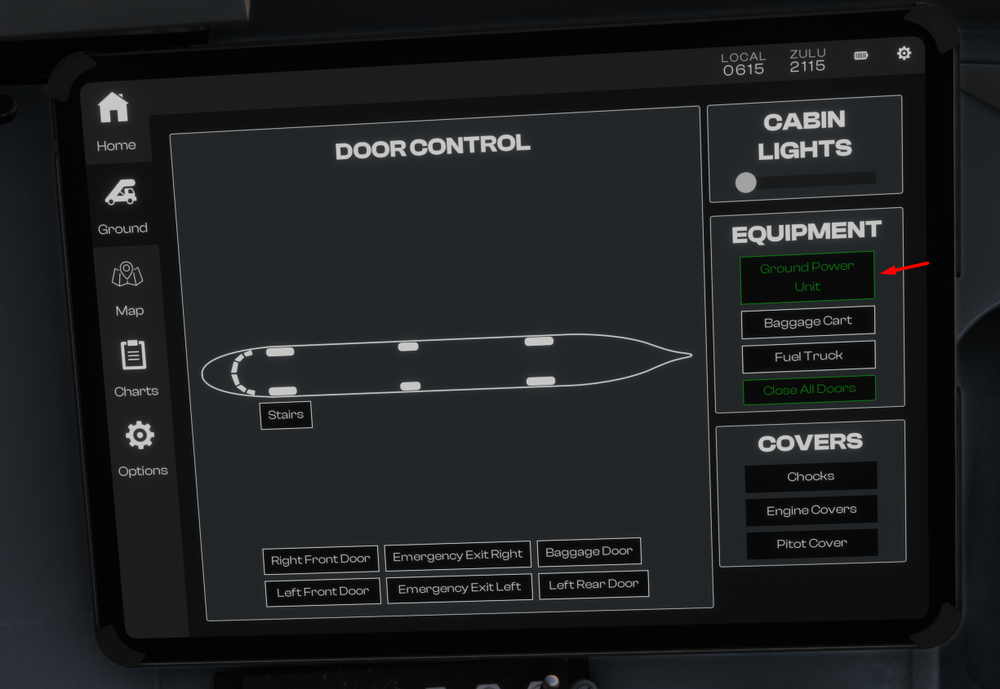
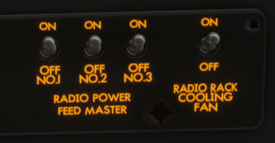
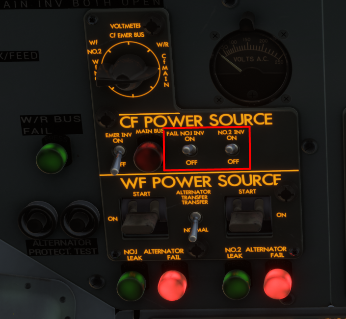
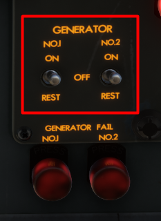
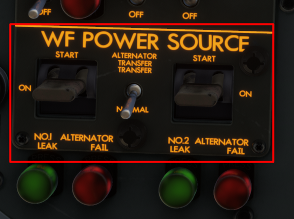
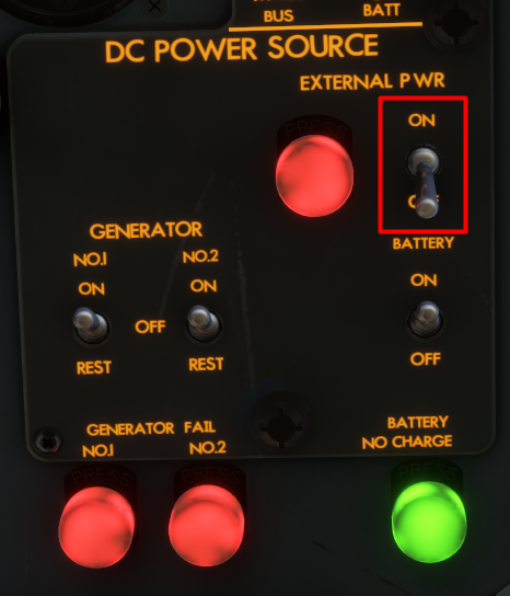
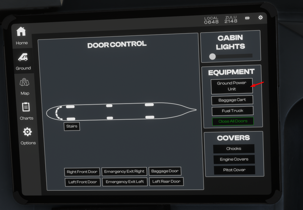
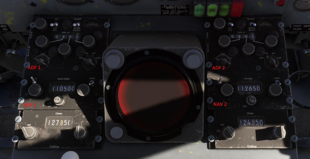
The YS-11 is equipped with 2x COM radios, 2x NAV receivers and 2x ADF Receivers. All of these can be tuned via controls found on the forward section of the Centre Pedestal (4) Forward Pedestal Radios ADF Frequency and Selector Knobs ADF Power Switch NAV Frequency and Selector Knobs NAV Power Switch NAV Ident Volume Knob COM Power Switch COM Frequency Selector Knobs WT GNS430 GPS If you are using the WT GNS430 GPS, the radio controls on the GPS are tied to COM3 / NAV3 only. Please use the radios on the pedestal only for communication / navigation. RADIOS - ELECTRICAL POWER To operate the radios and avionics, proper power source needs to be established, in addition to turning on their respective unit power switches. To establish electrical power on the ground, Turn on BATTERY Switch on the Overhead Panel Connect External Power via EFB + Turn on EXTERNAL POWER Switch on the Overhead Panel Turn on RADIO POWER FEED MASTER No. 1 / 2 / 3 switches on the Overhead Panel Turn on CF POWER - INVERTER SWITCHES NO.1 / 2 on the Overhead Panel Turn on COM / NAV / ADF power switches on the Center Pedestal After Engine start, Turn on the GENERATOR NO. 1 / 2 switches on the Overhead panel Turn on the WF POWER SOURCE - ALTERNATOR NO.1 / 2 switches by moving to START then ON position on the Overhead panel Turn off the EXTERNAL POWER Switch on the Overhead Panel + Disonnect External Power via EFB
-
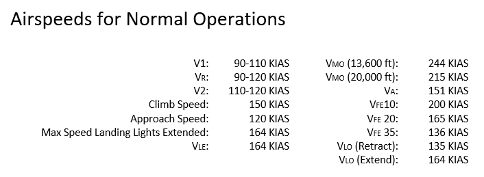
The following section is intended to supplement the Simplified Procedures or in-simulator Checklist. General operating guidelines are provided along with speeds and power settings to be applied per flight phase. Engine Start Ensure the Low Stop Lever is in the Ground position. Engine 2 is started first, followed by Engine 1. Engine 2 HPC lever: ON. Starter and Ignition panel: Engine Select No. 2. Starter Master: Start. Starter Push Button: Push and hold for 4 seconds, the button should remain in. When the RPM reaches 1200 to 1500 RPM: Engine 2 HPC lever to HSWL position. Repeat the procedure for Engine 1. After Start Starter and Ignition panel: Engine Select OFF. Starter Master SAFE (middle position). Set Flap 15, this is the normal Take Off Flap setting. Take Off Gently apply full power, note that the Low Stop Lever will automatically move to the Flight position as the power levers are advanced. Full power will be approximately 15,000 RPM. V1 and Vr speed is 90-110 KIAS depending on weight. Rotate gently, especially at high weights. Allow the aircraft to get airborne on its own and avoid the temptation to increase the pitch further if the aircraft does not become airborne immediately. Once airborne, Adjust your pitch accordingly to maintain a V2 speed of 110-120 KIAS. Retract the gear, turn the Landing and Taxi Lights OFF and retract both Landing Lights. At 1,000 ft AGL lower the pitch of the aircraft to accelerate. Set 14,200 RPM, retract the flaps. Establish a climb speed of 150 KIAS, this will correlate to approximately 1,000 FPM at Maximum Take Off Weight. Climb Throughout the climb monitor the speed and adjust the vertical speed accordingly to maintain 150 KIAS. If using the autopilot remember that there is no altitude preselector in this aircraft. Gently reduce the vertical speed and press ALT to engage altitude hold when your desired altitude is reached. Cruise Cruise RPM is the same as climb - 14,200 RPM. Set the HPC levers to the ON position. Monitor your fuel consumption and transfer fuel from the auxiliary tanks to the main tanks as required. Engine 1 is fed from Main Tank 1 Engine 2 is fed from Main Tank 4. Using the transfer pumps, transfer fuel from Auxiliary Tank 2 into Main Tank 1 and from Auxiliary Tank 3 into Main Tank 4. Descent Set power as required to maintain a speed of 200 KIAS. This will correspond to approximately idle power, and a vertical speed of -1,000 to -1,500 FPM. Approach and Landing On Approach, Reduce speed from 200 KIAS to 150 KIAS. Select Flaps 10 when the speed is below VFE. When appropriate (and below VLO of 164 KIAS), - Extend the landing gear - Extend the Landing Lights and turn them ON as well - Turn on the the Taxi Lights. - Set the HPC levers to HSWL position. Select Flaps 20 and continue to decelerate to the approach speed of 120 KIAS. Select Flaps 35 on final approach whilst maintaining 120 KIAS. At touchdown, Move the Low Stop Lever to the Ground position. Note: This lever can be operated using the “Toggle Spoilers” control assignment Apply brakes as required, remember that the YS-11 does not have reverse. Go Around In case of a go around, Apply Full Power (approx 15,000 RPM). Adjust pitch to maintain an initial pitch attitude of 10 degrees. Select Flaps 15. Note: that when heavy, the YS-11 will take time to accelerate. Monitor the pitch attitude and carefully adjust it to accelerate and prevent altitude loss as the flaps are retracted. Retract the gear when a positive rate of climb is achieved. At 1,000 ft AGL - Lower the pitch of the aircraft to accelerate - Set 14,200 RPM - Retract the flaps Establish a climb speed of 150 KIAS, this will correlate to approximately 1,000 FPM at Maximum Take Off Weight. Level off at desired altitude and then repeat the Approach and Landing section process.
-
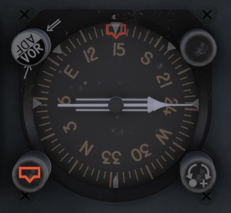
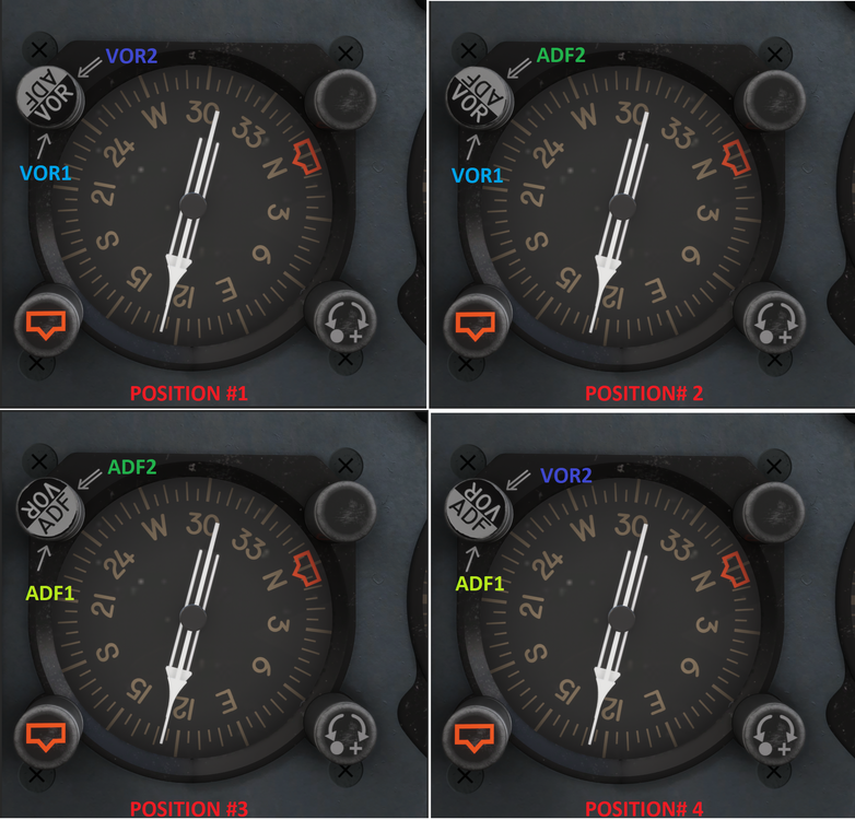
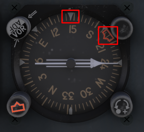
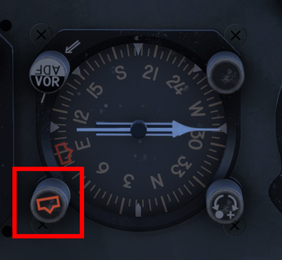
The YS-11 is equipped with a dual-needle Radio Magnetic Indicator (RMI) on each side of the cockpit that is used as both a bearing and heading indicator. RMI - Bearing Indicator The two needles always indicate magnetic bearing to the selected beacon (VOR or NDB) provided there is an active signal. The tail of the needle indicates the reciprocal bearing. You can configure the needles in a various number of ways using the Selector Knob positions as follows: Position #1 - The thin needle (single line) points to VOR1. The thick needle (double line) points to VOR2. Position #2 - The thin needle (single line) points to VOR1. The thick needle (double line) points to ADF2. Position #3 - The thin needle (single line) points to ADF1. The thick needle (double line) points to ADF2. Position #4 - The thin needle (single line) points to ADF1. The thick needle (double line) points to VOR2. RMI - Heading Indicator The RMI also functions as a heading indicator by using a slaved gyro to always show the direction of the aircraft in relation to magnetic north at the 12 o'clock position. There is additionally a Heading Selector bug that can be manipulated using the HDG Selector Knob at the bottom left to choose a heading target for the autopilot when using Heading Hold mode. Example - Current Heading 145 deg, Selected Heading 200 deg For more information on Autopilot Operation please refer to the manual or see:
-
Microsoft / iniBuilds - YS 11 Simbrief Profile: https://dispatch.simbrief.com/airframes/share/11223_1758809508331
-
Example Calculation For this example, we will consider a 200 NM flight • Departure airport elevation: Sea Level • Departure airport taxi time: 10 minutes • Arrival airport elevation: 2,000 ft • Cruise level: FL150 • Average climb wind: 20 kt headwind • Average cruise wind: 30 kt headwind • Average descend wind: 10 kt headwind Total Fuel Required Taxi: 300 lbs Take Off: 200 lbs Climb: 654 lbs Cruise: 997 lbs Descent: 420 lbs Approach fuel: 200 lbs Reserve Fuel: 1,400 lbs Contingency Fuel (5% of Take Off + Climb + Cruise + Descent + Approach): 124 lbs Total: 4,295 lbs Calculation Breakdown Taxi Fuel 10 minutes taxi at 30 lbs per minute: 300 lbs. Take Off Fuel Fuel required to reach 1,000 ft AGL: 200 lbs. Climb Fuel 150 KIAS will be maintained throughout the climb, leading to an increasing TAS as the altitude increases. For climbing it is common practice to consider the TAS at a point two thirds of the desired cruise altitude. In our case climbing from sea level to 15,000 ft, 2/3 would equal 10,000 ft. Extracting the TAS from the Climb table at 10,000 ft gives 240 KTAS. An average climb rate of 1,000 FPM will be assumed for calculation purposes. Take Off fuel accounts for fuel up to 1,000 ft AGL, therefore we will take 14 minutes to climb the remaining 14,000 ft to reach our cruise level of 15,000 ft. In this example we are assuming a climb headwind component of 20 kt, obtaining a resulting Ground Speed of 220 kt (240 KIAS – 20 kt). We will now compute the distance taken on the climb: 14 minutes at 220 kt = 51 NM. During the climb the average fuel flow is 2,800 lbs per hour. The climb will take 14 minutes, therefore requiring 654 lbs. Cruise Fuel Using the table provided we extract at 15,000 ft a cruise TAS of 250 kt and a fuel flow of 2,600 lbs per hour. Before we can compute our cruise fuel, we need to know the length of our cruise segment. The distance required to climb was calculated previously (51 NM), we now need to calculate the descent distance in order to compute the remaining cruise distance. Our arrival airport is at an elevation of 1,000 ft. From 15,000 ft we will need to descend 14,000 ft. Assuming a rate of descent of 1,000 FPM this equates to 14 minutes. Our TAS is required and this can be extracted from the table located in the Descent Fuel section. When descending we will consider the TAS at the halfway point throughout the descent. We will be descending 14,000 ft, half equates to 7,000 ft and we add the arrival elevation to this figure giving an altitude of 8,000 ft for our TAS. At a descent speed of 200 KIAS this corresponds to approximately 230 KTAS. The average descend wind is 10 kt headwind, giving a resulting Ground Speed of 220 kt. 14 minutes descending at 220 kt Ground Speed will cover 51 NM. Total flight distance of 200 NM, minus climb distance (51 NM), minus descent distance (51 NM) = 98 NM cruise distance. At our cruise level the expected headwind component is 30 kt. TAS 250 kt – 30 kt = 220 kt Ground Speed. 98 NM at a Ground Speed of 220 kt takes 27 minutes. 23 minutes at a fuel flow of 2,600 lbs per hour requires 997 lbs. Descent Fuel The descent distance and time was computed in the Cruise Fuel section: 14 minutes and 51 NM covered. Average descent fuel flow is 1,800 lbs per hour. On a 14 minute descent the fuel required is 420 lbs. Approach Fuel Standard Approach fuel required is 200 lbs. Reserve Fuel 30 minutes reserve fuel: 1,400 lbs.
-
An abbreviated method is provided to calculate the fuel required for your flight. Note that the values mentioned below are for total fuel required for both engines assuming Maximum Take Off Weight. An example calculation is provided for reference. Taxi Fuel 30 lbs / minute. Take Off Fuel 200 lbs required until reaching 1,000 ft. Climb Fuel 2,800 lbs per hour at a climb speed of 150 KIAS, approximately 1,000 FPM. Equivalent True Airspeed for 150 kt Indicated Airspeed: Altitude (ft) IAS (kt) TAS (kt) 20,000 150 210 15,000 150 195 10,000 150 180 5,000 150 165 Cruise Fuel Cruise power setting 14,200 RPM. The fuel flow remains approximately stable at 2,600 lbs/hr. Altitude (ft) IAS (kt) TAS (kt) Fuel Flow (lbs/hr) 20,000 190 265 2,600 15,000 190 250 2,600 10,000 190 230 2,700 5,000 190 210 2,700 Descent Fuel 1,800 lbs per hour. Speed of 200 KIAS, approximately 1,000 FPM at 12,500 RPM. Equivalent True Airspeed for 200 kt Indicated Airspeed: Altitude (ft) IAS (kt) TAS (kt) 20,000 200 280 15,000 200 260 10,000 200 240 5,000 200 220 Approach Fuel 200 lbs fuel required from 2,000 ft AGL at 200 KIAS, execute the approach and a Go Around until reaching 1,000 ft AGL in clean configuration. Holding/Reserve Fuel 2,800 lbs per hour, holding at 1,000 ft AGL at 200 KIAS.
-
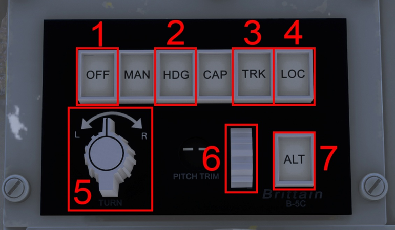
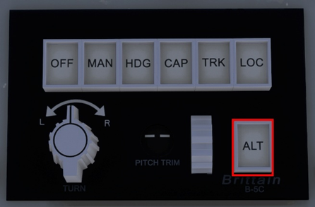
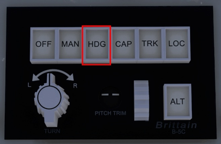
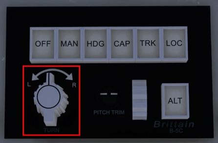
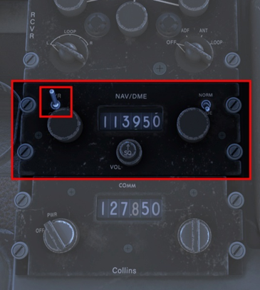
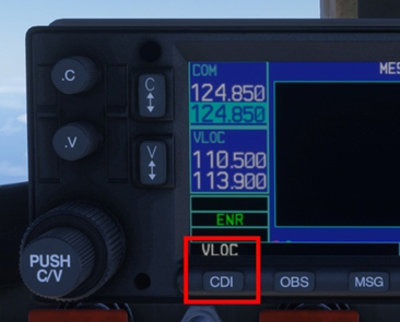
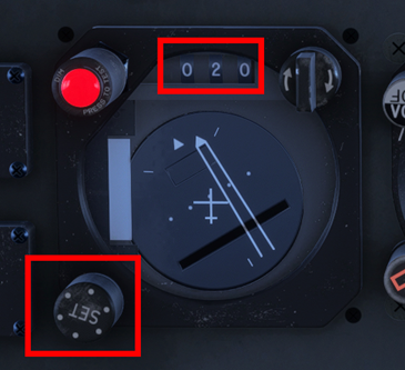
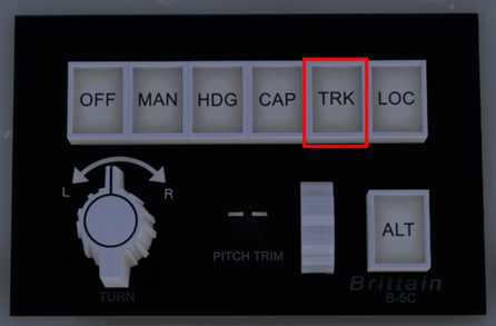
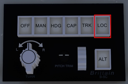
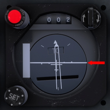
The YS-11 is equipped with the Brittain B-5C, three-axis Automatic Flight Control System—a robust, low-power autopilot designed to enhance stability and reduce pilot workload across roll, pitch, and yaw axes. The B-5C integrates seamlessly with the aircraft’s navigation system to provide smooth course tracking and altitude hold. Its simplicity, reliability, and minimal electrical draw make it especially well-suited for regional turboprops like the NAMC YS-11, where operational efficiency and mechanical resilience are paramount. Autopilot Control Panel 1) Autopilot Disengage 2) Heading Hold 3) NAV Hold 4) Localizer and Glideslope Hold (APPR Mode) 5) Turn Knob 6) Vertical Speed Selector 6) Altitude Hold Engaging the Autopilot The B-5C autopilot system lacks a dedicated master switch for activation. Instead, engagement occurs through the selection of a lateral mode—such as Heading Hold, Nav Hold, or Localizer Hold. Activating any of these modes automatically engages the Vertical Speed mode, maintaining the aircraft’s vertical speed at the moment of engagement. An alternative method of engaging the autopilot is through the Altitude Hold function. However, this activates only the altitude control—lateral guidance must be selected separately via Heading Hold, Nav Hold, or Approach Hold to achieve full autopilot functionality. Engaging Heading Hold Select the desired heading in the Directional Gyro using the Heading Knob. The knob can also be pushed to synchronize the bug to the current heading. Press HDG in the Autopilot Control Panel. Note: this will engage the Vertical Speed mode as well and maintain the vertical speed present at the moment of engaging Heading Hold. Engaging Altitude Hold Press ALT, this will command an immediate level off at the current altitude. Note: if the autopilot was not previously engaged only the ALT mode will engage. A lateral mode must be subsequently engaged if desired. Commencing a Climb/Descend Disengage the Altitude Hold mode if it was previously engaged. Turn the Vertical Speed Selector to select the desired vertical speed target. The target will be displayed as a tooltip and can be seen by placing your cursor over the selector. Using the Turn Knob If the autopilot was not previously engaged, engage it by first selecting Heading Hold. Turn the knob to the left or right to initiate a turn in the desired direction. When the desired heading is reached, turn the knob back to the middle (neutral position). Note: The turn will continue as long as the knob is not neutral. Capturing and Tracking a VOR Radial Tune the desired VOR in the NAV/DME radio. Note: ensure the unit is turned on. This is controlled by the top left switch. If using a GPS unit, VLOC must be displayed. If GPS is displayed, press the CDI button to change the guidance to VLOC. Select the desired course in the Course Deviation Indicator by using the lower left knob. The course is displayed at the top of the instrument (020 in this case). The top right knob reverses the set course by 180º. Press TRK to engage the mode. Capturing and tracking the GPS Route In your desired GPS unit, select GPS. If VLOC is displayed, press the CDI button to change the guidance to GPS. Press TRK to engage the mode. The autopilot will now follow the GPS guidance. Executing an ILS Approach Tune the desired ILS in the NAV/DME radio. Note: ensure the unit is turned on. This is controlled by the top left switch. If using a GPS unit, VLOC must be displayed. If GPS is displayed, press the CDI button to change the guidance to VLOC. Select the desired course in the Course Deviation Indicator by using the lower left knob. The course is displayed at the top of the instrument (020 in this case). The top right knob reverses the set course by 180º. Press LOC to engage the Approach mode. Note: the real autopilot was capable to only track the Localizer, hence the LOC text in the button. For ease of use it was decided to simulate the Approach mode (Localizer and Glide Slope tracking). The Glide Slope indication is shown in this image. The aircraft is on the Glide Slope when the horizontal white line is in the middle of the instrument.


-
Hi @kevinh Thanks for your report. If you can, please provide the OFP (PDF) for your route where you noticed this so I can share with the team for reproduction/fix testing. Thanks!
-
Hi all, Firstly, you should never delete the WASMs in the community folder. What you've done is essentially deleted all the code of the aircraft, so no wonder it doesn't work in that instance. Please DO NOT delete any files from the package in the community folder. You should uninstall and reinstall the package fresh from iniManager to ensure there are no missing essential files at present. When we ask you to clear your WASM folder, we only mean the sim-compiled WASMs that can be found on the AppData folder paths listed here: You are welcome to receive support but please refrain from making inflammatory statements. We apologize for your frustrating experiences but I assure you, as you said, "you shouldn't need to do any of this" as the product is working fine in this regard for majority of the customer base without CTDs. Your experience so far is the exception, not the universal norm, so please have some patience as we work with you (and others here) to figure out the cause of such issues on your install. The Windows crashdumps are very limited in their ability to diagnose or provide useful data when it comes to MSFS. Going by the above though, it points to some kind of potential error or corruption in virtual memory (pagefile). I know you have tried, but just for completeness sake, please can you can try the following in the way listed below: Uninstall A350 from iniManager then complete a fresh install of the latest (v1.1.4) Delete your FS20 AppData WASM folders from the paths listed here: Adjust Virtual Memory behaviour as per this link: https://forums.flightsimulator.com/t/flightsimulator-exe-application-error-0x80000003-a-breakpoint-has-been-reached/334962/101 If it was already on automatic, try manually setting a custom size that is 1.5x your physical memory (e.g. if you have 16GB RAM, try 24GB) Load into MSFS with just the A350 package (inibuilds-aircraft-a350) in your community folder. Spawn directly onto a runway in any variant. Observe if you get a CTD or WASM loads on launch. If you do have a CTD, please share the windows error log again as well as exactly where you tried. Again, most users don't have to do any of this but we are just going off the limited metrics available to us from your submitted crash reports to help you find a solution. This is very weird considering "broken" liveries will at best result in lack of selection for those liveries in the aircraft selection menu, not CTD the sim as a whole. The livery package, if unreadable, will normally just not load into the VFS. What were the liveries you had installed so I can try exactly that set to see if we can reproduce the issue? For context, I run FS20 A350 in testing regularly across 2 different systems (one PC, one laptop) with the entire FS20 IniManager liveries library installed on one system; and all the marketplace livery packs installed on another and have yet to experience such CTDs across the iniManager or Marketplace builds. What were the liveries you had installed so I can try exactly that set to see if we can reproduce the issue? If there is any action/fix required on our part, we're always eager to do it and push it via update, as we have throughout the life of this product. However, we can't fix an issue that we cannot reproduce, so we need your help to try these things and let us know so we can work together to find the cause (and also hopefully a solution). Thanks!
-
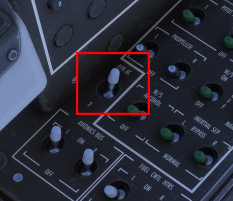
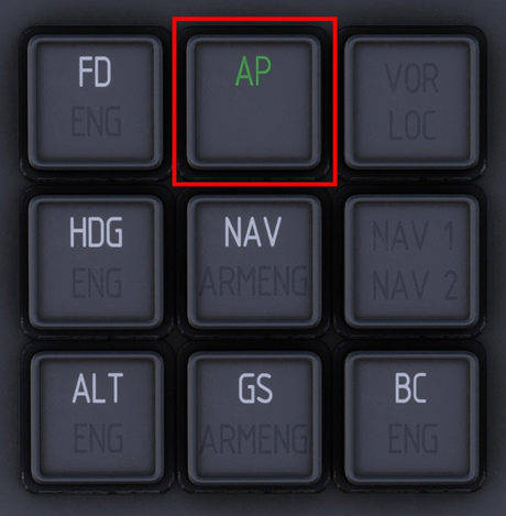
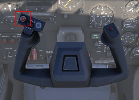
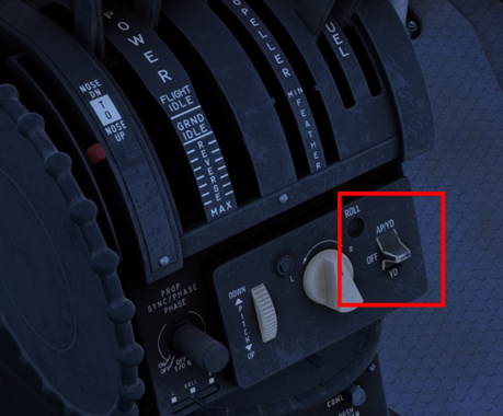
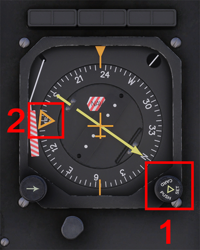
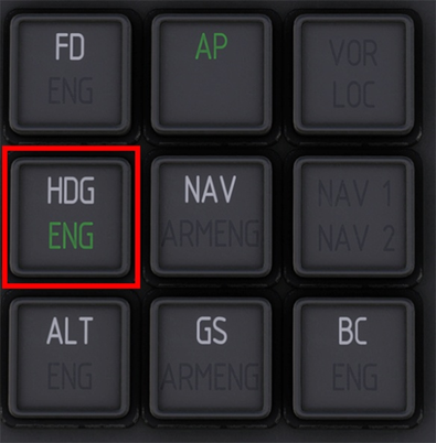
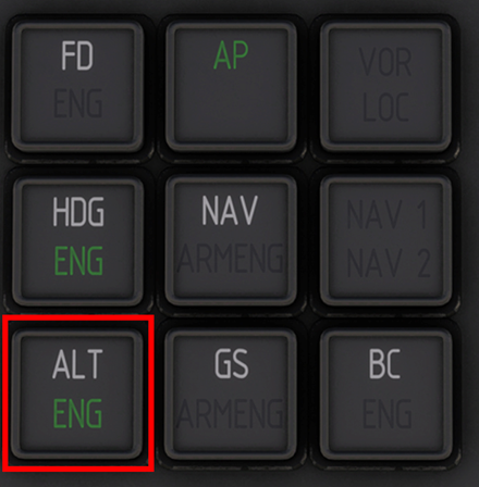
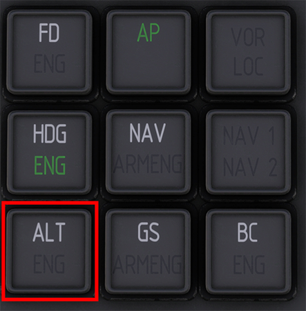
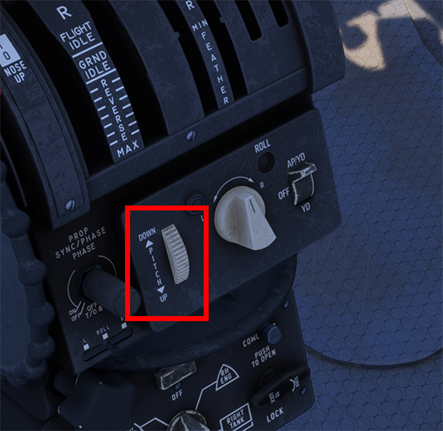
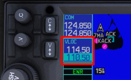
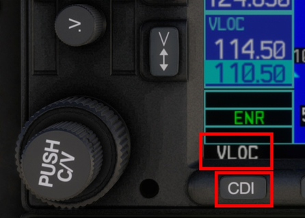
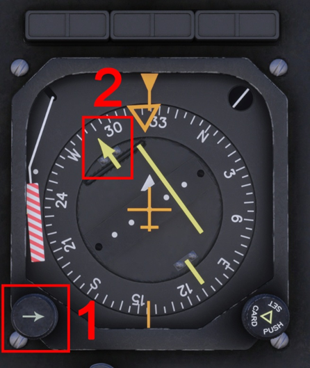
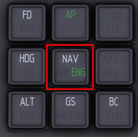
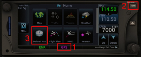
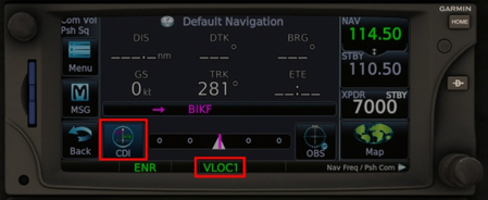
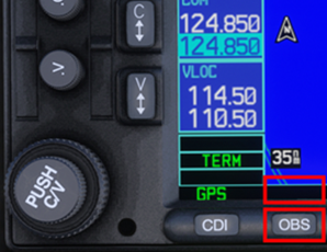
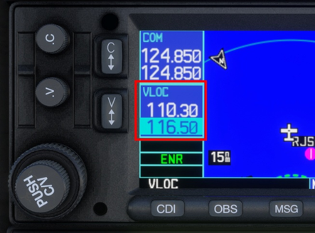
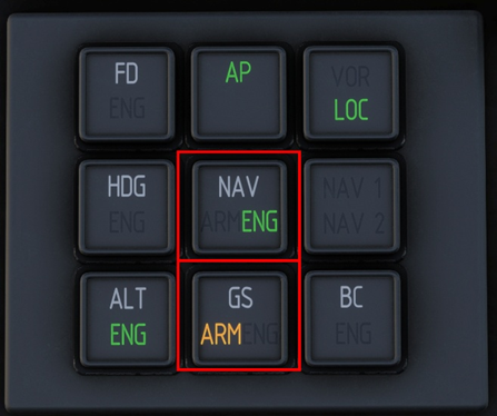
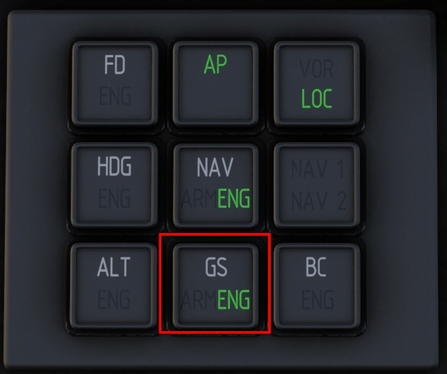
Overview The iniBuilds F406 has a two-axis autopilot that controls the ailerons and elevators. There is no auto-throttle, the power levers must always be controlled by the pilot to achieve the desired target power and/or speed. The Yaw Damper functions independently of the autopilot and can be engaged in conjunction with the autopilot or independently to provide basic yaw coordination. Engaging the Autopilot / Yaw Damper The F406 autopilot system comprises of two units: the Autopilot Control Panel and the Autopilot Mode Selector. Both units are used together as they provide different functionalities and modes of operation. 1. Ensure the Inverter is switched ON by selecting 1 or 2. There are two identical inverters installed in the F406. Selecting either one will provide the required AC power to the autopilot. 2. Select the desired AP/YD position on the Autopilot Control Panel. The AP Control Panel is found on the center console. Move the switch up to engage both AP/YD, or down to engage YD only. The system is OFF in the centre position. 3. Verify engagement on the Autopilot Mode Selector. Autopilot engagement is confirmed by the green AP indication. All the buttons on the AP Mode Selector also act as 'mode annunciators', indicating the status of the relevant mode being either ARMED or ENGAGED. Disengaging the Autopilot There are 3 ways to disengage the autopilot: Yoke Press the red Autopilot Disengage Button. Note: to re-engage the autopilot after using this button you must press it again to re-arm the autopilot. Center Console Select the OFF position on the Autopilot control panel. Keybind Assign a key or controller button to the AUTOPILOT OFF function via the control settings. Heading Hold Mode (HDG) In this mode, the autopilot captures and maintains the heading selected on your HSI using the HDG SEL knob. 1. Set your target heading. On the Horizontal Situation Indicator (HSI) use the (1) Heading Select knob to select the desired (2) target heading. 2. Press the HDG button. Press the HDG button on the Autopilot Mode Selector to engage Heading hold mode. The aircraft will turn towards and track the selected heading on the HSI. Engagement is confirmed when ENG is displayed on the button. Altitude Hold Mode (ALT) In this mode, the autopilot commands an immediate level off and maintains present altitude. 1. Press the ALT button on the Autopilot Mode Selector. Engagement is confirmed when ENG is displayed on the button. Note: The F406 autopilot does not have an altitude preselector and is only able to maintain the altitude at mode engagement. The preselector was optional and not installed as default equipment on this type. Commencing a Climb or Descent The simulated autopilot can maintain a desired vertical speed target set using the Pitch Command Wheel on the Autopilot Control Panel. 1. Ensure ALT is disengaged. If the Altitude Hold Mode (ALT) was engaged, disengage it by pressing the ALT button in the Autopilot Mode Selector. ENG will disappear when the Altitude Hold Mode is disengaged. 2. Use the Pitch Command Wheel to set desired vertical speed target. From the Autopilot Control Panel move the wheel up or down to select a higher or lower vertical speed target respectively to initiate and maintain a climb or descent. You can see your present target via the Tooltip or by observing your Vertical Speed Indicator (VSI) Tracking a VOR Radial or Localizer course (NAV - VLOC) The autopilot uses Navigation Mode (NAV) to capture and maintain the course selected on the HSI to a VOR or LOC. 1. Set desired VOR / LOC frequency on NAV1 radio. Select the VOR (or Localizer) frequency in NAV1 using your preferred GPS unit. 2. Ensure the GPS CDI is set to VLOC mode for tracking. GNS430 The active mode is displayed on the bottom left corner of the GPS unit. If GPS is displayed, press the CDI button to toggle to VLOC instead. GTN650 The active mode is displayed at the bottom of the GPS unit. If GPS is displayed, a. Press HOME button. b. Select Default Nav page. c. Press CDI button. d. VLOC1 will display as active mode. 3. Set desired course on the HSI. Use the (1) Course Selector Knob to select the (2) target course to be intercepted and maintained. 4. Press the NAV button on the Autopilot Mode Selector. The autopilot will now intercept and track your desired VOR or Localizer course. Engagement is confirmed when ENG is displayed on the button. Tracking a GPS Flight Plan The autopilot uses Navigation Mode (NAV) to capture and maintain the active GPS flightplan. 1. Ensure the GPS CDI is set to GPS mode for tracking. GNS430 The active mode is displayed on the bottom left corner of the GPS unit. If VLOC is displayed, press the CDI button to toggle to GPS instead. GTN650 The active mode is displayed at the bottom of the GPS unit. If VLOC1 is displayed, a. Press HOME button. b. Select Default Nav page. c. Press CDI button. d. GPS will display as active mode. 2. Load and activate your flightplan. If SUSP or OBS is displayed, press the OBS button until the indication above the button is blank. Note: the autopilot will NOT automatically sequence or follow the next leg otherwise. 3. Press the NAV button on the Autopilot Mode Selector. The autopilot will now intercept and track your GPS Flightplan. Engagement is confirmed when ENG is displayed on the button. Tracking an ILS The autopilot simulates a coupled approach (APP) mode via the NAV and GS buttons to capture and track the localizer and glide slope associated with an ILS. 1. Set desired ILS frequency on NAV1 radio. Select the ILS frequency in NAV1 using your preferred GPS unit. 2. Ensure the GPS CDI is set to VLOC mode for tracking. GNS430 The active mode is displayed on the bottom left corner of the GPS unit. If GPS is displayed, press the CDI button to toggle to VLOC instead. GTN650 The active mode is displayed at the bottom of the GPS unit. If GPS is displayed, a. Press HOME button. b. Select Default Nav page. c. Press CDI button. d. VLOC1 will display as active mode. 3. Set desired course on the HSI. Use the (1) Course Selector Knob to select the (2) target ILS course to be intercepted and maintained. 4. Press the NAV and GS buttons on the Autopilot Mode Selector. The autopilot will now intercept and track the Localizer. The Glide Slope mode (GS) is ARM until the Glide Slope is captured. Engagement is confirmed when ENG is displayed on the button. Glide Slope mode (GS) mode is now ENG, Altitude (ALT) mode automatically disengaged, and the autopilot is now tracking both the Localizer and the Glide Slope.
-
Overview The iniBuilds A350 Airliner for FS2024 (PC) now comes with additional Cabin Packs that you can download via the iniBuilds Store and soon via the Marketplace (PC). Once installed, you can choose one of the many custom airline cabins to use with any compatible livery of your choice via the Aircraft Selection Menu. Changing Cabin Variants Open the Aircraft Selection Menu Find from the list or Search for the 'A350' Choose the 'A350-900' or 'A350-1000' aircraft Select 'Configure' at the bottom left corner of your screen via your mouse or by pressing the shown keybind Choose the 'Variant' tab at the top Select 'A350-900 (XXXX)' or 'A350-1000 (XXXX)' variant, where XXXX is the desired airline cabin. Switch to the 'Livery' tab at the top Choose your desired livery from the list Select 'Save and Back' at the bottom left corner of your screen via your mouse or by pressing the shown keybind Now you can return to the Free Flight menu and select Start Flight to use the selected Cabin variant of the iniBuilds A350 Airliner. Cabin Variant FAQ Video.mp4 Compatibility with Custom Cabin Textures You can use any cabin variant with any installed livery for that aircraft type (-900 or -1000) as they share the same exterior models (e.g. Cathay Pacific -900 Livery with a Qatar Qsuite Cabin option). However, if your installed livery comes with additional cabin customizations/textures, they may conflict with the Cabin Packs. In such instances please use the "Default Cabin" variant to continue enjoy those customizations.


-
Hi, We have some testers who have used this aircraft in VR primarily since pre-release (both sims) without any major issues, even going in-and-out throughout longer flights. There is a known sim limitation specifically in VR or when using headtrackers/camera shake addons (like FSRealistic) that affects the accuracy of hit registration of mouse clicks on the MFD, which is being worked in FS24 SU3 Beta based on user reports. Please confirm that the aircraft is functional in 2D, if not, try to clear your WASM folder and launch directly onto a runway on first load to ensure proper WASM compile. Thanks!
-
Hi @GuangDu The manual is attached here, and also in the Resources/Documentation folder inside the aircraft package (Community Folder) : You need to ensure the weapon is armed first. Thanks
-
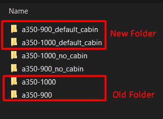
As of iniBuilds A350 Airliner update v1.0.11 (MSFS 2024), some necessary changes have been made to the folder structure in preparation for the ULR update. This affects the Cabin variants specifically, meaning that your previously saved custom camera configs (Cameras.cfg) may not load automatically on first load of this version. You can restore your Camera config by copying it over to the new folder as follows: Locate your Presets folder at the path listed below: There will be up to 6 folders. Your old Camera config is stored in the 'a350-1000/config' or 'a350-900/config' folder for -1000 or -900 Cabin variant respectively. Copy the Cameras.cfg from the Old folder to the to the New folders - 'a350-1000_default_cabin/config' or 'a350-900_default_cabin/config' for -1000 or -900 Cabin variant respectively.

-
Close the simulator if it is running. Navigate to your your FS20 WASM Folder: Steam: MS Store: Delete all the contents of this folder. This folder and its contents will be re-generated next time you load into a flight with the aircraft. Note: This will reset your EFB Throttle Calibration and EFB Settings so they should re-done the next time you load into the aircraft.
-
Sweet. if you have any further question regarding your transfer request (after submitting it), feel free to reach out to Direct Support: https://inibuilds.com/pages/contact
-
Hi @K2rockall Unfortunately there is not much in the logs there, however judging by the Exception code: 0x80000003 in the first screenshot, perhaps you can try the solution suggested there: https://forums.flightsimulator.com/t/app-could-not-start-exception-code-0x80000003 This appears to be a general sim issue due to missing dependencies rather than something A350 specific per se. If you continue to have issues, I recommend reaching out to MS Support as well with your logs for suggestions. Thanks!
-
Hi, The KJFK Enhanced upgrade is exclusive to purchases via the iniStore for the moment. We'd like to offer similar upgrade pricing paths via the FS2024 Marketplace, however still awaiting such functionality for it so not possible at the moment. If you're on PC and want to avail the discount pricing sooner than that you may Transfer your 2020 Marketplace purchase to iniStore via an Order Transfer: https://forms.inibuilds.com/order-transfer After successfully transferred, purchase 2024 KJFK Enhanced via the inStore using the same account that has 2020 JFK + use discount code KJFK- UG on checkout. Note: This will move your 2020 KJFK to iniStore permanently, and it will no longer be available via the Marketplace. Thanks!
-
Hi @Eric Jeppesen Just a follow up on your report. Can you please provide screenshots of how your axis is setup within the FSUIPC AXES & ASSIGNMENTS & CALIBRATION window? Both the assignments tab and also the calibration. I'm assuming the Paddles are the TWCS type, wherein they are a single axis? If so, how are you assigning it to brakes as an axis? Do you have it assigned to both LEFT BRAKE and RIGHT BRAKE in FSUIPC, then you have manually set the MIN / MAX values of the axis? And is the issue that both brakes are being pressed or just that its not "zero-ing" brake pressure in the centre? Thanks!

-
Hi @LineDX I've even tried loading into your autosave file but not seeing this (though as mentioned noted your issue). Will see if can be reproduced on any testers systems but in any case I don't expect this to be a major bug. Even if you are getting that on spawn it shouldn't affect flight at all as the aircraft mainly re-trims after engine start as you have mentioned. For anyone else reading this thread, this automatic trimming will usually happen after you have done the following: Update your weights via OIS LOADSHEET page (SET ZFW and SET FUEL) Fill in the FUEL & LOAD Page of the FMS (especially ZFWCG) with new values After engine start, observe automatic re-trim to the managed trim value. Troubleshooting: In case it does not set the correct value, DISARM and then ARM your ground spoilers again to trigger the auto-trim process again. Should be fixed in 1.0.8 As for VNAV in general, team is working on a larger update to the logic that will improve VNAV calculations and ALT CSTR compliance. This will come in a future update (1.0.9 at the earliest, though may be later as its still undergoing refinement and testing process). Thanks already logged and team is actively working on it. The TCAS STBY ECAM can be triggered by any of the following, ‐ Select STBY in the TCAS mode option list on the SURV CONTROLS page of the MFD, or ‐ Select STBY in the XPDR mode option list on the SURV CONTROLS page of the MFD, or ‐ Set the ALT RPTG button to OFF on the SURV CONTROLS page of the MFD. As its status is controlled by more than just the TCAS mode (TA/RA), probably what happened in your case is as follows - You set the TCAS mode from TA/RA to STBY - The ALT RPTG button also automatically set itself to OFF (by design) - You set the TCAS mode from STBY back to TA/RA - The ALT RPTG button remained OFF (by design) So ensure none of the following are set STBY or OFF to make the ECAM disappear. Reported. Thanks!

-
Thanks, issue is logged and team is actively working on it. Please confirm after reloading your autosave that - A/THR is enabled on the FCU - Your throttle axis is in the CLB detent - FMA reads SPEED / MACH / THR IDLE / THR DCLB depending on phase of flight as an indication of thrust control Your hardware input of primary flight controls, particularly throttle axis prior to loading the autosave can affect the status of that control after reloading. Hardware inputs will override the autosave variable always (same as it does in active flight). Thanks!
-
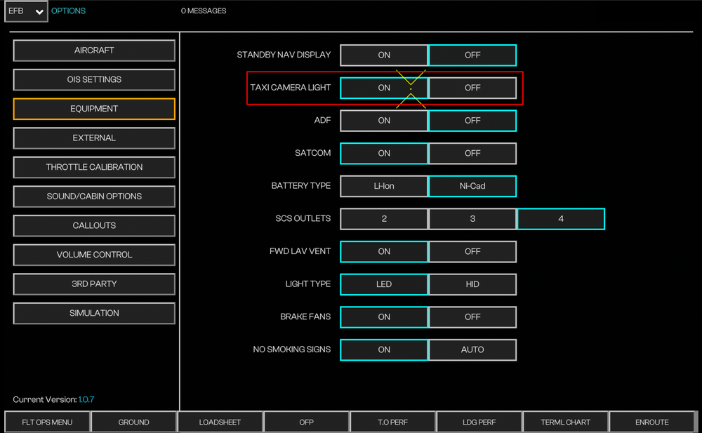
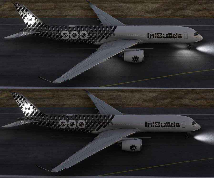
Since v1.0.6 update of the iniBuilds A350 Airliner, the Taxi Camera Lights are only operational on aircraft that have such lights installed; and when specific conditions listed below are met. Taxi Camera Lights - ON vs OFF (Click to enlarge image) To Enable Taxi Camera Lights You must ensure all of the following: Under OIS Equipment Settings > Taxi Camera Light is set to ON; and (Click to enlarge image) TAXI pushbutton on EFIS CP is set to ON; and (Click to enlarge image) NOSE LT switch is set to TAXI or T.O.; and Main Landing Gear (MLG) is on the ground


-
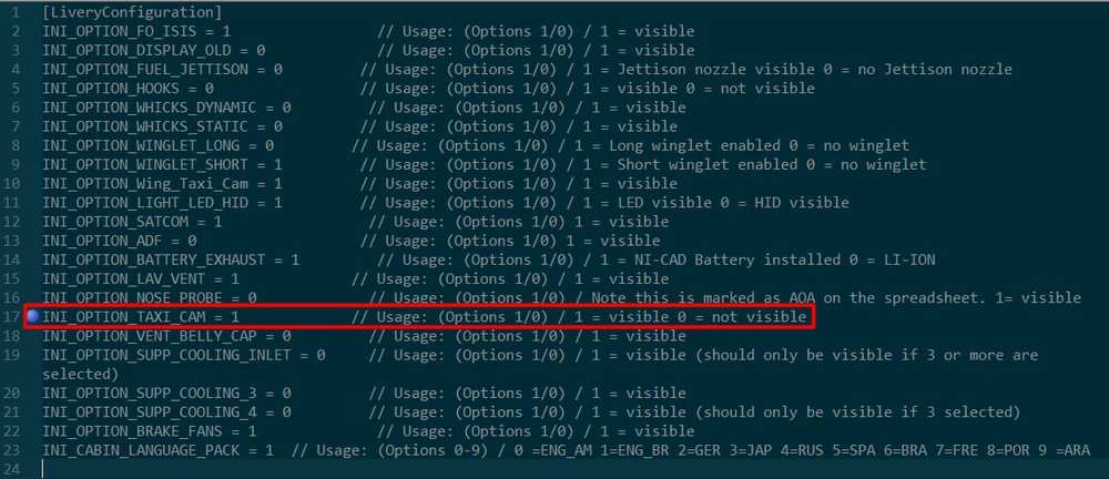
Since v1.0.6 update of the iniBuilds A350 Airliner, the Taxi Camera Lights are only operational on aircraft that have such lights installed; and when specific conditions listed below are met. Taxi Camera Lights - ON vs OFF - FS20 (Click to enlarge image) To Enable Taxi Camera Lights You must ensure all of the following: Under OIS Equipment Settings > Taxi Camera Light is set to ON; and (Click to enlarge image) TAXI pushbutton on EFIS CP is set to ON; and (Click to enlarge image) NOSE LT switch is set to TAXI or T.O.; and Main Landing Gear (MLG) is on the ground
-


