


richboy2307
Staff
-
Joined
-
Last visited
Everything posted by richboy2307
-
Re-download the latest version of this livery via iniManager. |It correctly shows under PW Freighter variant and engines only.
-
-
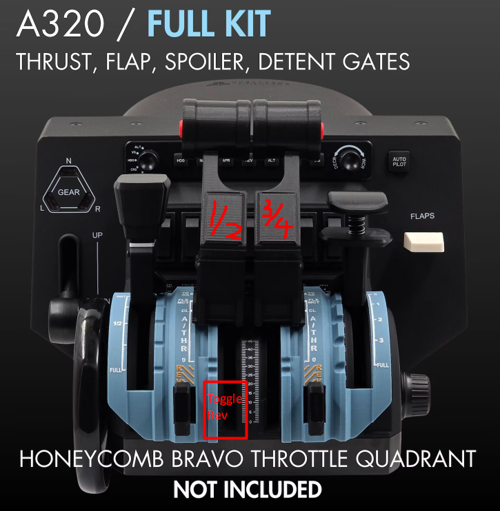
Hey @C. Schaffhausen Could you please share your FSUIPC7.ini file? I’d like to load it and try your setup, as I also have the Bravo TQ setup via FSUIPC. As far as I know, the Bravo TQ doesn’t have a dedicated axis for reversers, so it should be mapped to the standard throttle axis (THROTTLEX_AXIS_SET_EX1) in FSUIPC. You can use various button triggers for reverse thrust—either to "HOLD" max reverse thrust while the button is pressed OR to "TOGGLE" the reversers and then adjust the normal throttle axis accordingly to control reverse thrust input. On my setup I’m using the third-party "FlightSimFactory A320 PRO v3" throttles as dual-axis controls Dual Axis are mapped to 2 engines on either side, and The bottom detent of "left" lever as a "TOGGLE" for reversers, and Dual Axis are used to control reverse thrust output after the toggle, and reverted to forward thrust after re-initiating the toggle. (Click to enlarge image) Here’s a snippet from my profile for reference: Thanks!
-
Hi Thanks for your report. We'll investigate but please note that we have limited control over what AI Traffic or addons do, as we cannot specify particular pathing for them. The SDK tools only allow us to define basic information such as the location of runways, their start and end points, and the placement of taxiways. There is no option for more detailed control over AI or User Aircraft movements. Thanks.
-
Hi, Thanks for your patience. Your report is logged.
-
Hi Thanks for your patience. Certain gates are used for static aircraft, and they are disabled in the AFCAD to prevent AI traffic from spawning on top of these statics. You can disable the statics 3D model, however there is no secondary AFCAD for these airports as such the gates remain "unavailable". There are only few such gates across the sea of other available gates at this airport. Thanks
-
-
Hi all, Thank you for your patience. We’ve taken note of the performance feedback shared here and the team will be investigating potential areas for improvement. Temporary tips to try if not already, while the team continues investigating: Lower Texture Resolution and TLOD/OLOD Verify that no duplicate scenery entries exist in My Library (can occasionally happen after updates). Disable various options from the Scenery Configuration Panel like Interior Clutter, 3D People, GSE or 3D Vegetation to help Thanks!
-
Hey Thanks the issue is logged and the team will look into it. Yes helipads are known to cause such random conflicts with jetways. We saw something similar with our own KJFK scenery as well. From our testing it seems like the following gates are affected: Gate C50, 51, 51L, 52, 53, 53L Thanks!
-
Hey, You need to disable the Microsoft/Asobo OMDB scenery via My Library. You can see below guide on how to do so. https://flightsimulator.zendesk.com/hc/en-us/articles/17373373933340-How-to-enable-disable-and-download-content-in-the-simulator If that is not working, you can try to manually disable it via your Content.xml. In particular you want both these entries to read as either SystemDisabled or UserDisabled. Content.XML - Common Paths In there you will see a folder that is named after your XBOX user id. The content.xml file should be in it. Mine for example is richboy2307#6098. Save a copy for backup, and then edit with notepad as suggested above. Thanks!
-
Hi This was by design to avoid duplication of POIs (Burj Khalifa Building) at the site. We were unable to exclude the default POI at the time (Feb 2025), however we take note of your suggestion and will re-asses if its possible now. Thanks!
-
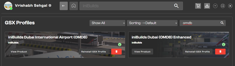
The VDGS at OMDB Enhanced is done via GSX. You just need to ensure you have downloaded the latest GSX Profile via the iniManager. Just ensure you get the one for OMDB Enhanced Thanks!
-
Hi Thanks for your patience. Other users have reported this is caused by an outdated/incompatible spinner mod. Please remove/update the mod. See for more details:
-
Thanks for your report, its been logged.
-
Same answer as posted in FS24 Support. See:
-
Fixed as of v1.0.7 Update
-
Apologies for delay in response, but issue is logged for further investigation. Thanks!
-
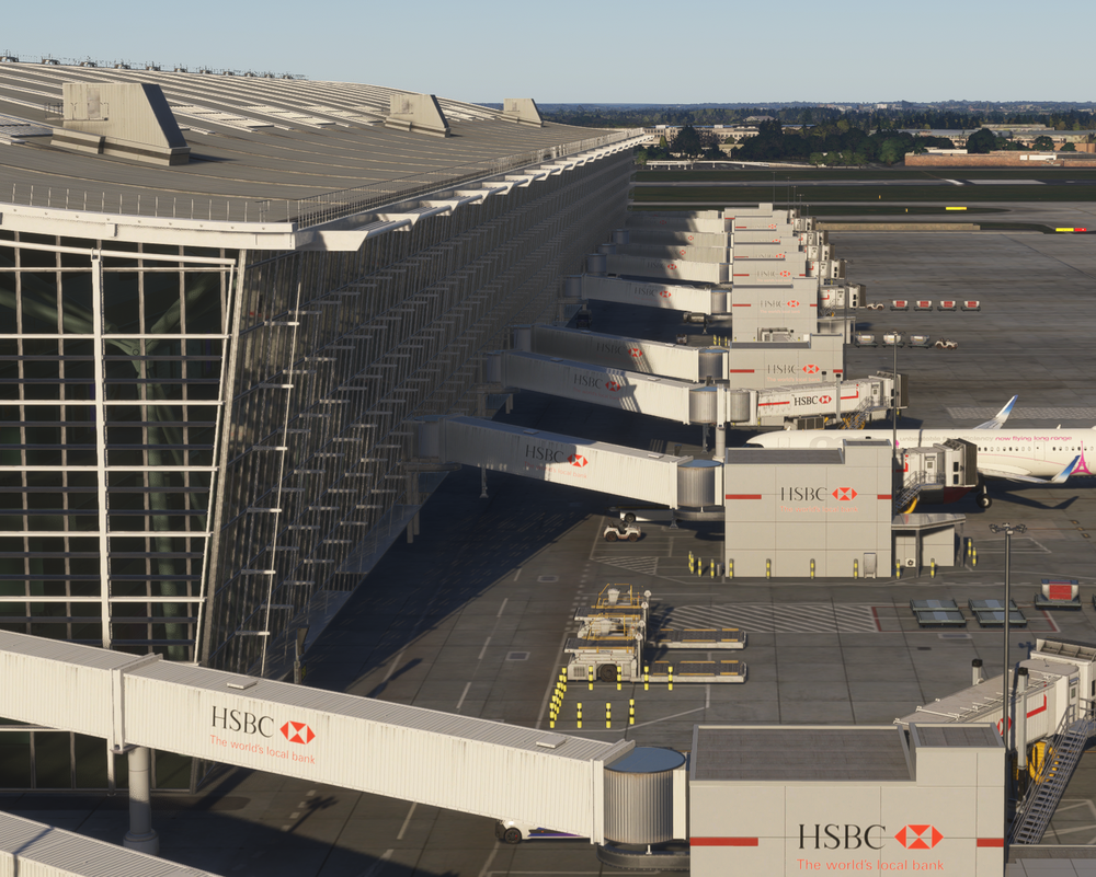
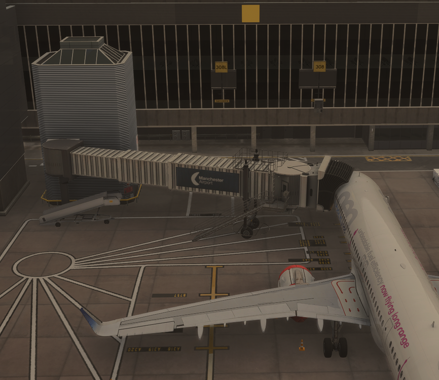
Hi Sorry for delay in response. Missing Red Horizontal Lines on T5A Jetway extensions - Logged for the dev team, the bug was reproduced Missing Logos / Plain White on T5A Jetway extensions - We cannot reproduce this issue on either HD/SD textures or with/without terminal interiors (see above image for ref). - The issue maybe because of a package conflict - either duplicated EGLL scenery installed or another installed scenery affecting the model/textures used. - Please verify via My Library that no other instance of EGLL is active. - To rule out other addon conflicts, try running with just EGLL in your community folder. Rename your existing Community folder (e.g. _Community), create a new one and place only inibuilds-airport-egll-heathrow inside. Clear your scenery indexes and load into EGLL to verify. To restore after testing, delete the new Community folder and rename your old folder back to Community. New HSBC Logo Your suggestion is noted. However please understand that our scenery was made with best available references we had at the time during development and the logos at present reflect that. Advertisements in particular are dynamic by nature and will keep changing over time so there will always be an element of "inaccuracy" in that regard with the digital twin counterparts. Thanks!
-
Hi We do not have any planned POI additions at the moment but your suggestion is noted for future development. Thanks!
-
Hi No there are no hand-placed static aircraft with this scenery. Thanks!
-
Hi, No we do not advertise the scenery as compatible. Thanks!
-
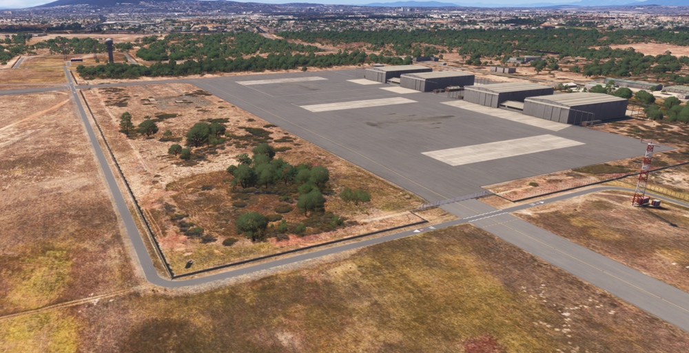
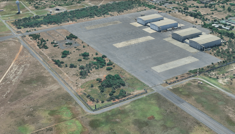
Hi, This is by design. That area of the ramp and taxiways are not openly accessible. They're fenced off and guarded similarly IRL as well. Unfortunately due to sim limitations and particular layout of the runway, the sim-ATC or add-ons may try to route you this way but in reality will not be possible or issued either. Thanks
-
Hey thanks for your report. Will forward to the team. If you have any additional reference photographs (IRL, not sim) to share, it would be helpful.
-
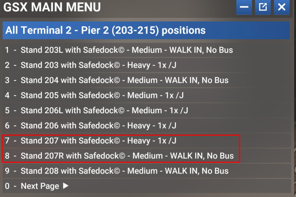
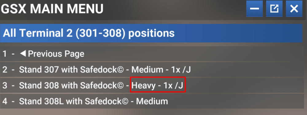
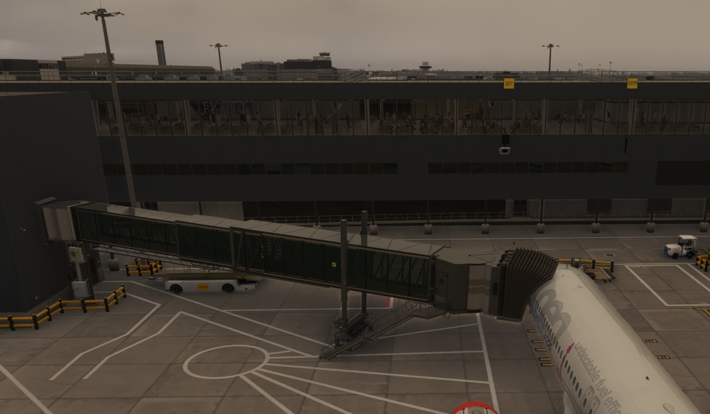
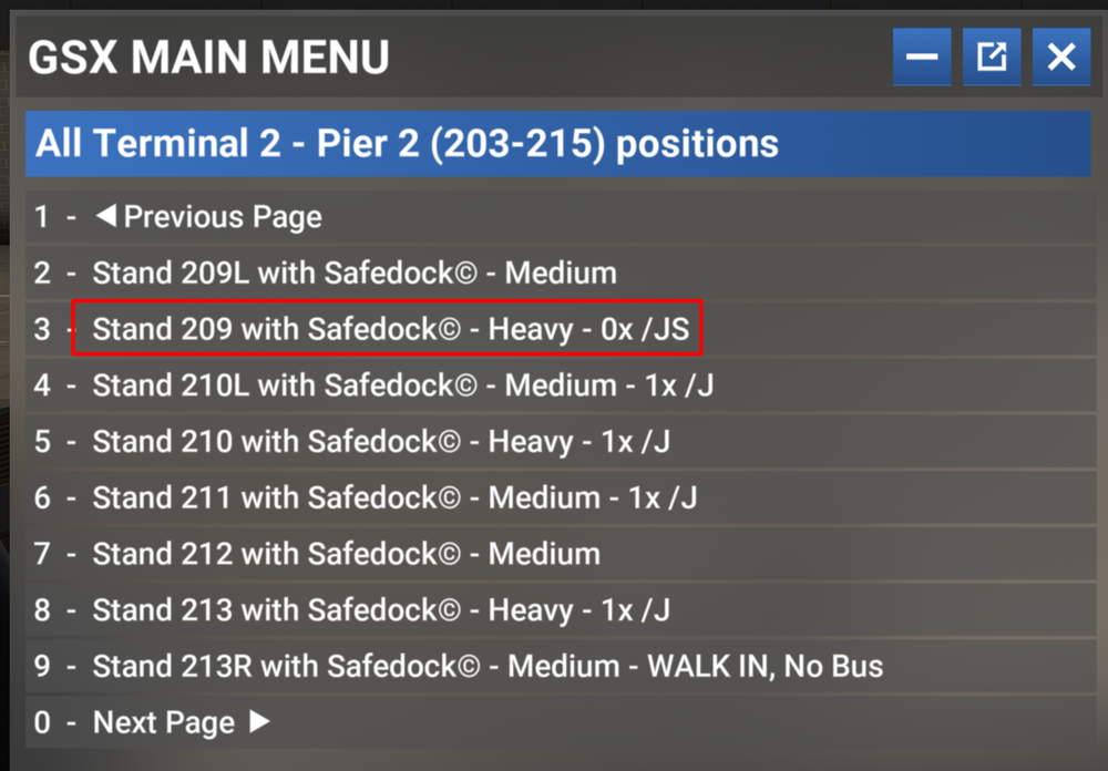
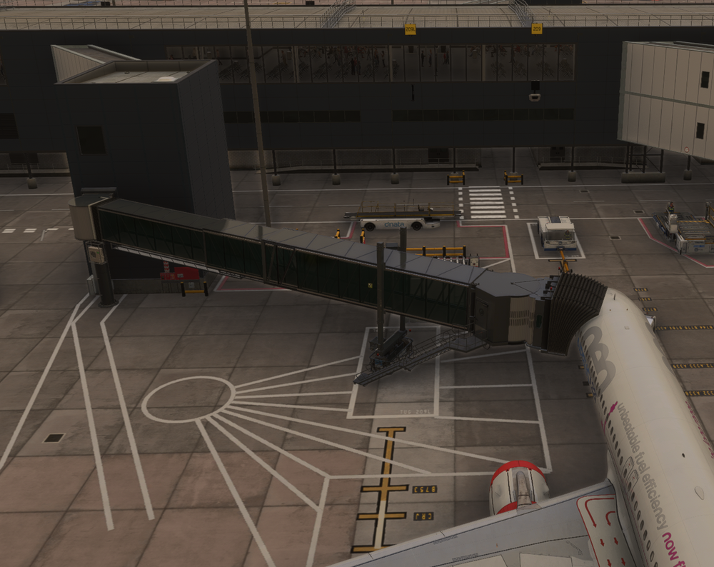
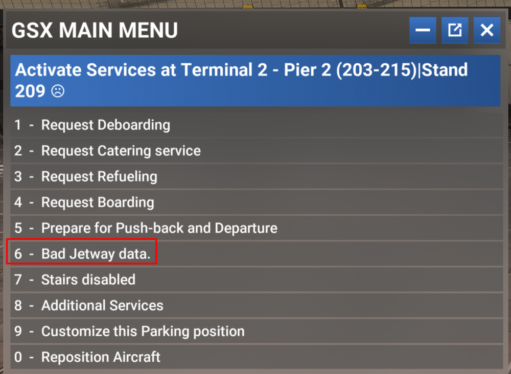
Hey Liam, Thanks for your report. 'No Jetways Here' Due to a sim limitation we are limited to just 1 jetway per gate. We cannot attach multiple jetways to the same gate , nor can we to attach the same jetway to multiple different gates. You can see the same in the GSX Gate Selection menu. The gates with jetways are indicated with 1x/J. 'Invalid Jetway Data' These might be a GSX profile bug. These will be seen as 0x/J on GSX. So for the reported instances: 308/308L - The jetway there is assigned to main gate (308) while the side gate (308L) is stairs only. 'No Jetway Here' is expected for 308L. 207/207R - The jetway there is assigned to the main gate (207) while the side gate (207R) is walk-in only. 'No Jetway Here' is expected for 207R. 209/209L - The jetway there is assigned to main gate (209) while the side gate (209L) is stairs only. 'No Jetway Here' is expected for 209L. However I do see that GSX cannot access Gate 209 and showing 'Bad Jetway Data'. The jetway itself is working directly via EFB request or sim ATC request as defined in the scenery though. Gate 209 seems to be the only affected gate in the entire scenery. Logged this for the team. Thanks!
-
Hi Sorry you experienced this, but appreciate the report! Hopefully your other flights have gone more successfully. The autosaves are only created if the option is enabled in the settings and engine is running. As you crashed before start, its likely why. Based on the screenshots, it looks like T7 Gate 4 (F4) at KJFK. We’ve tried spawning there ourselves. We also tested this multiple times on different PCs internally, but we haven't been able to reproduce the WASM crash with the information provided as yet. Attached is a video from one of our attempts. We have also tried with variations such as - No fuel & payload loaded - IRS still in alignment - IRS not aligned It would be helpful if you notice anything we could try differently, or if you could provide a similar video showing the console window open at the moment the WASM crash occurs for you. This information is essential for us to try to reproduce the crash and work towards a solution. Thanks! 2026-01-20 03-28-29.mp4


