


richboy2307
Staff
-
Joined
-
Last visited
Everything posted by richboy2307
-
As mentioned above, we have been trying but don't have any viable workaround at the moment for what appears to be a platform-level bug with how its rendering the clickspots. Should we find one that works, it will be pushed via an update but barring that it remains an issue that needs addressing sim-side. Thanks!
-
A known issue since SU5 Beta, please see:
-
Now you can. Try on v1.0.9. If you do happen to get a crash, please follow this guide to report the CRASH variables as well.
-
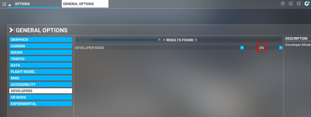
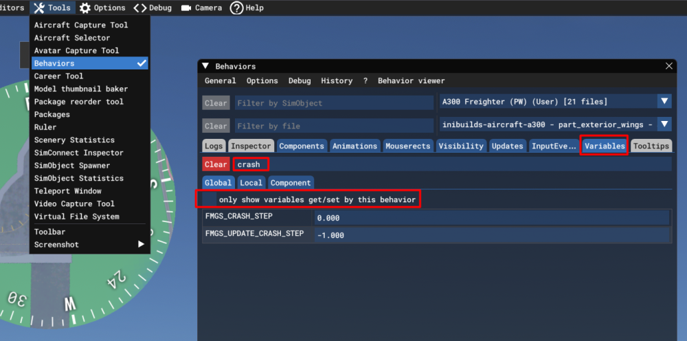
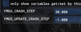
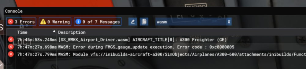
What is WASM?The WebAssembly Module (WASM) is a container for running programmes written in other langauges (eg C/C++) that is then converted to native code ahead of time (as DLLs) during first launch (WASM Compilation). This helps improve performance for subsequent uses but causes longer load times on first launch. his also improves security of the sim and portability of projects across PC / Consoles. In case of issues, only the WASM crashes instead of the rest of the sim along side with it. This is why the sim and some functions may continue to work, however other systems and displays that use WASM on the aircraft become unresponsive or "freeze" in place with a red warning screen. So what to do in case of WASM crash?Do not close the sim/restart flight immediately Verify the WASM error message & crash LVARs Report the WASM error message & crash LVARs with reproduction steps using the guide below. Verify WASM Crash in SimStep 1. Enable Developer Mode FS24 Settings > General > Advanced Options FS20 Options > General Options > Developers Step 2. Enable the Console by pressing "~" key on your keyboard or using the Dev Toolbar at the top of the screen Step 3. Filter the Console by ❌Error messages only by clicking on ⚠️Warning and ℹ️Messages to disable them (remove blue box border around them). Step 4. Type 'WASM' in the search box. Find the WASM Error and Copy the message. Also take a screenshot of this console window for making a report. Step 5. Check the new CRASH LVARs via the Behaviours Menu. Also take a screenshot of this for making a report. Accessing Behaviours Menu FS24 Via the DevMode toolbar at the top, select Tools > Behaviours and navigate to the Variables tab. Uncheck "Only Show Variables get/set....". Type 'CRASH' in the search box and expand their name to display the values. Report WASM Crash on ForumStep 6. Paste the WASM Error message, screenshot of the Console and INI_CRASH LVARs obtained in Step 4 and Step 5 above into a forum post/discord message/ support ticket WASM Crash Report. Step 7. Take note of what you pressed or things you did, just before you noticed this crash happen. Step 8. Verify if you are able to repeat the crash by following those same steps. Step 9. Please provide the following information Aircraft: A300 PW Freighter Simulator: FS2024 Navdata Method: SIM DEFAULT or NAVIGRAPH BASE OFP: Include a PDF of your Operational Flightplan (OFP) if related to FMS/Route Procedures crashes WASM Error: The error you copied in Step 4 above Crash Variables: The variables you screenshotted in Step 5 above Specs: CPU, GPU and RAM of your system. Step 10. Include on your report a Screenshot / Video showing what you pressed/did just before the crash happened to give us more clues. Screenshot of the Crash Variables Steps on how to reproduce the crash so that we can try ourselves with debugging tools to identify the cause of crash. These types of WASM crashes are heavily dependent on the actions taken just before the issue occurs. Detailed reports of the exact steps leading up to the crash are extremely helpful, as if we’re able to reproduce the issue internally using the same sequence, our team can investigate, debug, and resolve it much more effectively.


-
This would be useful yes, along with exactly the airport at which you tried and with what approach. Normally if you're in ALT mode already, arming LOC then ILS should properly set the aircraft up for a GS intercept from below.
-
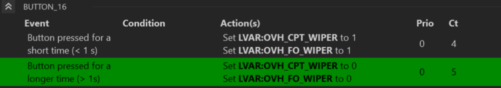
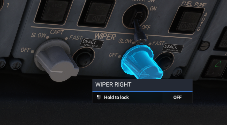
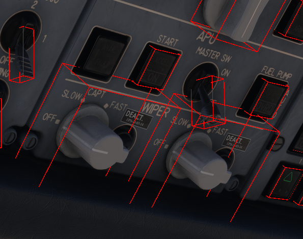
Try these: L:OVH_CPT_WIPER and L:OVH_FO_WIPER 0 = OFF, 1 = SLOW, 2 = FAST I dont have Axis and Ohs but checked via SPAD and both seem to be working. Yes they do work. The DEACT sticker is referring to the rain repellent switches, not the wipers themselves. Their clickspot however is currently affected by a platform level bug since SU5 beta that incorrectly scales the clickspots of certain types of XML interactions. The same was reported on A310 and taken by Asobo as a sim bug - basically the click spot boundaries have become too small / scale incorrectly with zoom levels, resolutions etc. In these instances the clickspot will always be exactly at the center of the switch. Move closer or zoom in if you're having troubles for the time being. You can confirm this by enabling Developer Mode > Tools > Behaviours > Debug > Interactions. You'll note that the interaction shows, and works as intended but the hitbox seemingly de-scales wrongly when the debug is disabled.
-
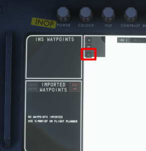
The display map will show at position 0,0 until Alignment is completed , AND MSU Mode Select knob is set to NAV, AND Execution of TK CHG in AUTO or MNL mode from 00 to 01. All of these are necessary to initialize the system. You can then re-center the map to your actual position by clicking the aircraft icon. Because when you spawn on the runway, it automatically aligns the INS to your present position. The map in the center is an INS DISPLAY MAP, its driven by coordinates from INS1, 2 or 3 respectively. Its not a GPS map that is always aware of your position. So when you spawn at a gate, cold and dark, it places the purple dot at 0,0 as it has no known position until the alignment and initialization process is completed as per above.
-
Once we get more clarity on the PS5 Marketplace and it's process we'll be able to say more but yes, we intend to support the platform with our addons. There is no ETA but I'm sure we'll make an announcement once that happens. Stay tuned to our socials or newsletter which you can sign up for at the bottom of our store page: https://inibuilds.com/

-
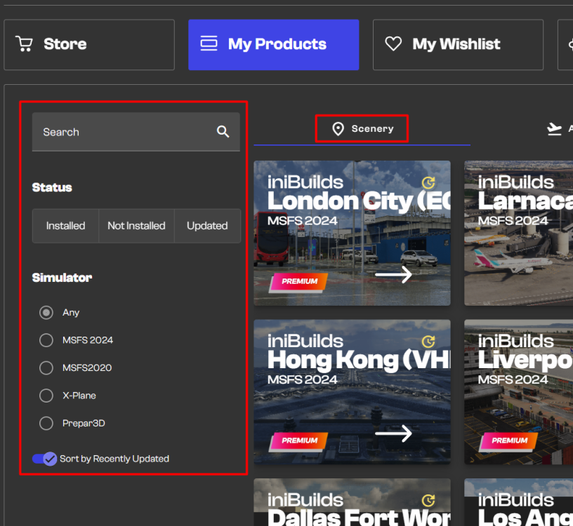
Hi, Ensure you're logged in to the same account where you purchased the addon. Click on My Products from the toolbar on the left. Select the Scenery tab and ensure no status, simulator or search filters are selected. You should see your purchased PHNL copy there if the order was paid for successfully. If not, please reach out to Direct Support with reference to your order# and use the same email as your registered account. https://inibuilds.com/pages/contact Note, much of the team is currently attending FSExpo so expect some delay in responses as they travel to return to office in the coming week. Thanks!
-
Hey That is the plan but expect more finalised information closer to release. And yes it is safe to expect special Emirates liveries. They're truly the airline synonymous with A380 after all with that enormous fleet!
-
-
Thanks, those features were deemed beyond the scope of this product line and the price is reflective of that. However we note the suggestion for future development. As for the A380, expect features on par with the A350 at the very least, if not more :) Thanks!
-
Hi @heyado7018 Thanks for your video. We tried reproducing your issue but no luck across the team or testers. See attached video of my personal attempt. We suspect the issue could be one of A keybind conflict - check all keybinds pertaining to Mixture, Fuel or Ignition. Alternatively try with just mouse and keyboard connected to rule this out. An assist conflict - ensure automixture is disabled under Settings > Assistances as it can affect availability of fuel An addon conflict - you tried running Tristar with a renamed (assuming empty) community folder so less likely in this particular instance. Let us know if any of the above suggestions work? Thanks 2026-06-09 01-31-02.mp4
-
Yes the physical probe equipment on the engine may be the similar, and what they can physically measure will be equivalent but the computers that process this data before being shown to the flight crew are nowhere near the same. As far as the Tristar is concerned, all the available resources show that it cannot and will not show any indications lower than 1.0. Even if the actual pressure maybe lower than that, it will remain at 1.0 indicated at the very lowest. That being said, descent FLT IDLE readings are typically around 1.05-1.15 range depending on atmospheric conditions so I don't see any cause for alarm.
-
Hi, No even at IDLE when stationary, a running engine can't give an EPR below 1.0 - which indicates that the total exhaust pressure precisely matches the ambient intake pressure. A flight idle of ~1.100 is pretty typical.
-
You can use the following default events/keybinds to map the various light switches on the overhead panel. Function Default Event Name Event ID Landing Lights LANDING LIGHT ON LANDING LIGHT OFF TOGGLE LANDING LIGHTS LANDING_LIGHTS_ON LANDING_LIGHTS_OFF LANDING_LIGHTS_TOGGLE Taxi Lights TAXI LIGHTS ON TAXI LIGHTS OFF TOGGLE TAXI LIGHTS TAXI_LIGHTS_ON TAXI_LIGHTS_OFF TOGGLE_TAXI_LIGHTS Strobe Lights STROBES ON STROBES OFF TOGGLE STROBES STROBES_ON STROBES_OFF STROBES_TOGGLE Beacon Lights (ANTI-COLL) BEACON LIGHTS ON BEACON LIGHTS OFF TOGGLE BEACON LIGHTS BEACON_LIGHTS_ON BEACON_LIGHTS_OFF TOGGLE_BEACON_LIGHTS Nav Lights (POSN) NAV LIGHTS ON NAV LIGHTS OFF TOGGLE NAV LIGHTS NAV_LIGHTS_ON NAV_LIGHTS_OFF TOGGLE_NAV_LIGHTS Wing Lights WING LIGHTS ON WING LIGHTS OFF TOGGLE WING LIGHTS WING_LIGHTS_ON WING_LIGHTS_OFF TOGGLE_WING_LIGHTS Logo Lights TOGGLE LOGO LIGHTS TOGGLE_LOGO_LIGHTS All Lights TOGGLE LIGHTS ALL_LIGHTS_TOGGLE
-
You can use the following default events/keybinds to map the various buttons on the glareshield autopilot panel. Note: Some functions are not mapped due to lack of available equivalent in the sim. Use of Simconnect Event IDs is recommended over direct LVAR, however also provided for reference. AFCS Panel AFCS Switches Description Default Event Name Event IDs (Simconnect or LVAR) AUTOTHROTTLE AT Toggles AT Mode AUTOPILOT AIRSPEED HOLD AP_AIRSPEED_HOLD INI_AP_AIRSPEED_HOLD TM Toggles Thrust Management (TM) Mode when at least one AP is in CWS or CMD - - IAS Selector Knob + Increases the IAS mode speed target INCREASE AUTOPILOT REFERENCE AIRSPEED AP_SPD_VAR_INC IAS Selector Knob - Decreases the IAS mode speed target DECREASEAUTOPILOT REFERENCE AIRSPEED AP_SPD_VAR_DEC PITCH VNAV Toggles VNAV mode - - VS Toggles VS HOLD mode at current vertical speed when pressed TOGGLE AUTOPILOT VS HOLD AP_VS_HOLD INI_AP_VS_HOLD VS Selector DN Decreases the VS mode pitch target DECREASE AUTOPILOT REFERENCE VS AP_VS_VAR_DEC INI_AP_VS_VAR_DEC VS Selector UP Increases the VS mode pitch target INCREASE AUTOPILOT REFERENCE VS AP_VS_VAR_INC INI_AP_VS_VAR_INC ALT Toggles ALT HOLD mode at current altitude when pressed TOGGLE AUTOPILOT ALTITUDE HOLD AUTOPILOT ALTITUDE HOLD ON or OFF AP_ALT_HOLD INI_AP_ALT_HOLD AP_ALT_HOLD_ON AP_ALT_HOLD_OFF IAS Toggles IAS HOLD mode at current IAS when pressed - - MACH Toggles MACH HOLD mode at current MACH when pressed TOGGLE AUTOPILOT MACH HOLD AP_MACH_HOLD INI_AP_MACH_HOLD HEADING HDG Toggles HDG HOLD mode to command turn to selected heading TOGGLE AUTOPILOT HEADING HOLD AP_HDG_HOLD INI_AP_HDG_HOLD HDG Selector Knob + Increases the HDG mode target INCREASE HEADING BUG HEADING_BUG_INC HDG Selector Knob - Decreases the HDG mode target DECREASE HEADING BUG HEADING_BUG_DEC - CPT FD Switch Toggles the Captain's Flight Director guidance TOGGLE FLIGHT DIRECTOR TOGGLE_FLIGHT_DIRECTOR FO FD Switch Toggles the First Officers's Flight Director guidance - - TURB Toggles Turbulence mode when atleast one AP is in CWS or CMD - - AP A Switch Toggles Autopilot A between OFF and CMD Modes TOGGLE AUTOPILOT MASTER Note: To disconnect autopilot use AUTOPILOT OFF to actuate the yoke AP Disconnect Button twice and silence any wailers AP_MASTER AUTOPILOT_OFF AP B Switch Toggles Autopilot B between OFF, CWS and CMD Modes - - NAVIGATION ILS Toggles APPROACH or APPROACH/LAND Modes, arming both LOC and GS capture and tracking TOGGLE AUTOPILOT APPROACH HOLD AP_APR_HOLD INI_AP_APR_HOLD LOC Arms Localizer capture and tracking TOGGLE AUTOPILOT LOC HOLD AP_LOC_HOLD INI_AP_LOC_HOLD VOR Arms VOR Course capture and tracking AUTOPILOT NAV1 HOLD AP_NAV1_HOLD INI_AP_NAV1_HOLD CRS 1 Selector Knob + Increases HSI Course pointers for ILS, LOC, BC and VOR modes on Captain's Side INCREASE VOR1 OBS VOR1_OBI_INC CRS 1 Selector Knob - Decreases HSI Course pointers for ILS, LOC, BC and VOR modes on Captain's Side DECREASE VOR1 OBS VOR1_OBI_DEC CRS 2 Selector Knob + Increases HSI Course pointers for ILS, LOC, BC and VOR modes on First Officer's Side INCREASE VOR2 OBS VOR2_OBI_INC CRS 2 Selector Knob - Decreases HSI Course pointers for ILS, LOC, BC and VOR modes on First Officer's Side DECREASE VOR2 OBS VOR2_OBI_DEC INS Toggles INS course capture and tracking TOGGLE WATER RUDDER TOGGLE_WATER_RUDDER BC Arms Localizer Back Course capture and tracking TOGGLE AUTOPILOT BACKCOURSE HOLD AP_BC_HOLD INI_AP_BC_HOLD ALTITUDE ALT Selector Knob + Increases Altitude Target by 100ft, will accelerate by 1000ft when repeated INCREASE AUTOPILOT REFERENCE ALTITUDE AP_ALT_VAR_INC INI_AP_ALT_VAR_INC ALT Selector Knob - Decreases Altitude Target by 100ft, will accelerate by 1000ft when repeated DECREASE AUTOPILOT REFERENCE ALTITUDE AP_ALT_VAR_DEC INI_AP_ALT_VAR_DEC
-
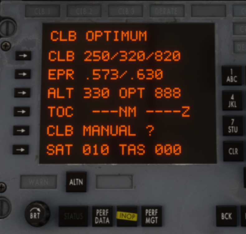
Thanks issue is logged for further review. I was able to reproduce. The same axis assigned via FSUIPC or Mobiflight doesn't exhibit such behavior for me which is puzzling. Logically if the axis input was being blocked/intercepted by the aircraft code then it should not work via any external tool 😅 Anyways, for the time being assign via the sim directly to work around the issue.Above 60 kts, tiller and nosewheel operation inhibited, which is most likely what you're experiencing. Any rudder axis input above 60 kts will only move the rudder. Tiller (Nosewheel Steering) Axis will not be operational. In v1.0.7 there is an Flight Model update coming to give more effectiveness to rudder alone but the rest appears to be by design and not a result of any hydraulics. Please verify against the 60kts threshold for what you're experiencing.Hey @zbrainlezz That is odd, I do have both and I'll check as well. I've been using mine bound via FSUIPC7 at the moment so I do know it can be controlled externally, but will see if can reproduce the above issue via SPAD specifically. Based on video alone seems like while Bravo is active, its sending commands but once it stops giving commands, another device thats still at idle is then taking over perhaps? Can you confirm there isn't another connected device that is being read by the sim (or SPAD) also sending thrust commands, thereby creating a conflict with each other? Thanks!Are you referencing the EPR target set on the glareshield in TM Mode specifically? If so, observe on the PMS when you're seeing this behaviour, and you'll note whats happening when it "drops again" is its shifting from MAX CL (CL1) to NORM CL EPR (CL2) values as the target. The way its modelled now is it will try to use calculated CL2 table values for your weight, temperature and altitude ranges. If outside the tabled parameters, it will instead use the calculated CL1 values for your current weight, temperature and altitude. It will transition back to CL2 if within tabled parameters at the next update point. Using this image example from above again, the calculated CL2 and CL1 values at the moment are .573 and .630 respectively. It will command only either of those (+- 0.001 EPR) in TM mode. Yes, the IRL counterpart behaves the same way automatically modulating between the CL modes - except - there is more specificity in the logic for conditions that must be met before the switch happens. That additional conditional specificity as well as manual mode selection is not currently simulated. We have it on our wishlist for systems we'd love to add depth to given the development time, but it is beyond the initial scope set for the product. What is simulated is the essence of how the actual unit works - i.e that it references current conditions against MAX CLB EPR (CL1) and NORM CLB EPR (CL2) performance tables for -500 stored within the PMS database AND automatically modulates commanded EPR between CL1 and CL2 based on periodic data-comparison to obtain the nominal climb rate. Yes according to the team what we have currently is set based on the -500 performance data available to us. For all parameters such as EPR, N1, Fuel Flow etc. For the sluggish climb rate you are expecting - try manually controlling your throttles exactly per the NORM CL values shown on the PMS at various stages and see if you still have the issue. If so, please advise with screenshots or video reference of exactly what you're seeing in sim vs roughly what you'd expect at the various stages so we can investigate further. Yes you don't have -500 specific data but if you make an estimation of the expected result based on your -100 data, we can run a comparison against the data we have and verify if the sim is exhibiting that or not to determine any adjustments required. We also appreciate your reporting, and are not trying to be dismissive of it but random image comparisons such as that provided are also not conclusive in establishing tangible data for resolution/adjustment without also equally full knowledge of all the parameters such weight or atmospheric conditions as you mentioned.
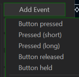
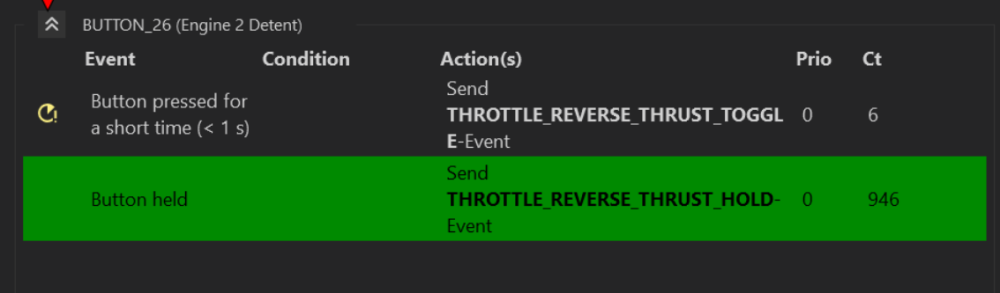
 Hi @Joshua Green The team is not able to reproduce this currently. 20260519-2130-32.7561892.mp4 | Could you please provide additional details as follows What waypoints you had loaded in at the time exactly - FROM/TO Your approximate position What was the new waypoint entered and in what WPT POS? A video or screenshots showing the process so we can try to repro exactly. Thanks!Noted. For now, you can use independent axis for modulation of rev thrust within IDLE REV and MAX REV ranges after reverser engagement - they all toggle together from IDLE to IDLE REV and back. In normal A-B flying, there are rarely situations that require engaging individual thrust reversers. Additionally, failure or abnormal situation simulations are not the primary focus of this product line hence why it was not a high priority during development. You can actuate them in unison using the listed HOLD or TOGGLE commands below as of 1.0.6: Depending on what you're doing you may need to adjust the trigger between BUTTON PRESSED, RELEASED or HELD accordingly. I use the Bravo myself and have it set to TOGGLE reverse thrust on one of the bottom detent buttons (26) on the throttle levers. This allows me to control the reverse thrust amount for each engine using independent throttle axes after having toggled it once. While they will toggle together, you can still apply asymmetric reverse thrust within IDLE REV to MAX REV range once you have independent axes assigned. The reversers are toggled back to forward IDLE thrust using the same button. I could also set it to HOLD reverse thrust when held (bottom option), that way once I push it down into the detent, it engages max rev as long as the button remains active/held.
 Yes ensure the MASTER RADIO ESSENTIAL and NO.2 are engaged. We have also identified some other specific scenarios which may cause it to stop working in SU5 due to JS conflicts - expect a fix in v1.0.7. Appreciate your patience meanwhile. Thanks!


