


richboy2307
Staff
-
Joined
-
Last visited
Everything posted by richboy2307
-
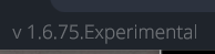
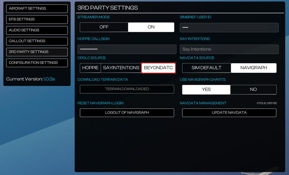
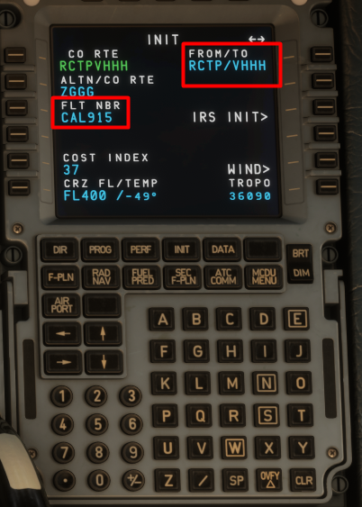
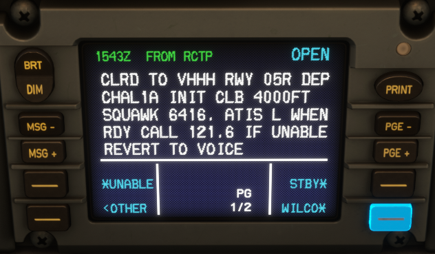
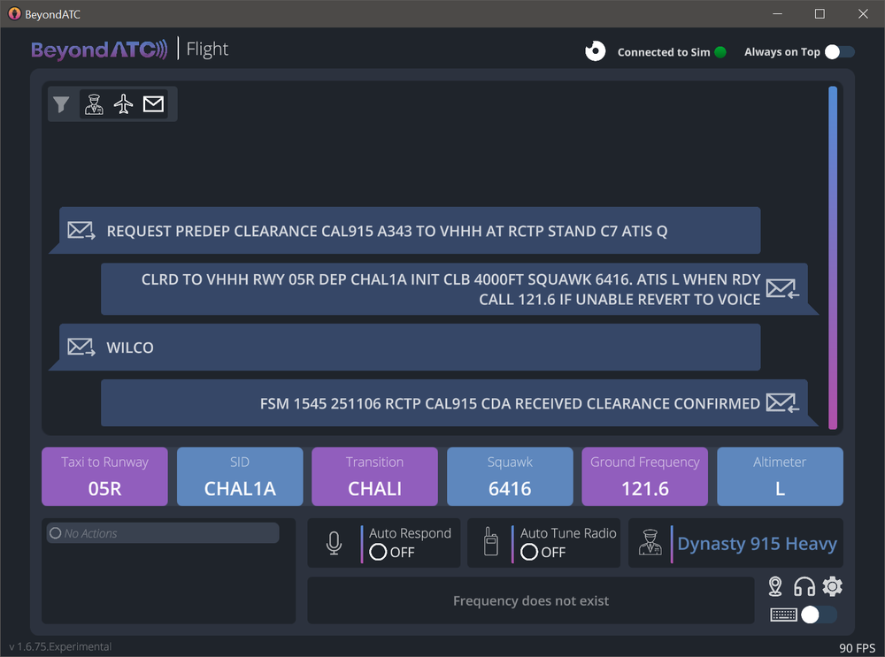
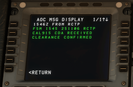
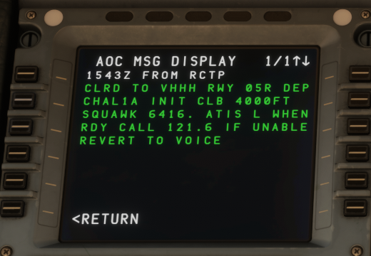
Hi @Donald Douglas/ @MMAACCXX Apologies for delay in response. For BATC, it only supports Pre-Departure Clearance (PDC) via CPDLC currently. Key things to ensure for proper function: You are on BATC Experimental Branch (v1.6.75 Experimental or greater). PDC is not available on the Early Access branch at this time. You have set BEYONDATC as the CPDLC Source on the EFB 3RD PARTY SETTINGS Page. (Click to enlarge image) You have completed your MCDU INIT-A page with information such as FLT NBR and FROM/TO After that, you can request PDC following the guide below: We and a few other testers have confirmed this working since launch, even up to v1.0.2 recently. Thanks!
-
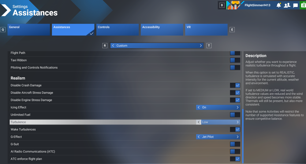
Hi @sgb478 That is very odd and not normal. Not seeing any widespread reports of any of the listed issues, nor have we seen that in our own testing. Additionally, there are no drastic changes implemented in the updates that would cause such a vastly different experience compared to release either. So something else has to be amiss here. CTDs are very likely related to unstable GPU driver or corrupted shader caches if you're receiving DXGI_Hung errors shown above. For everything else it could be a result of bad update or cached files. Not all driver versions are created equally, and not all of them work stably across the spectrum of GPUs. Try the latest first, but it may not always be the best so try to google for last known "stable" version for your particular GPU. Can you also please try the following Close the sim and manually delete the A340 (fs24-inibuilds-aircraft-a340) from your Streamed Packages folder. When you relaunch the sim next, it will initiate a fresh download/streaming of the package. The paths will be as follows: Steam: %APPDATA%\Microsoft Flight Simulator 2024\StreamedPackages\fs24-inibuilds-aircraft-a340 MS Store: %LOCALAPPDATA%\Packages\Microsoft.Limitless_8wekyb3d8bbwe\LocalState\StreamedPackages\fs24-inibuilds-aircraft-a340 Set Turbulence to LOW via Settings > Assistances menu. This is to avoid AP Disconnection due to exaggerated turbulence effect on CFD aircraft like the A340. Ensure control profiles have not reset during any sim update, and the correct ones are still applied to the A340. Increase your Rolling Cache size to atleast 2x your installed physical RAM (i.e. 32GB Rolling cache if you have 16GB RAM). This will flush the cache initially to rid of any out of date data, and also help ensure a smoother experience when dealing with streamed packages. Try conducting ILS approaches at different airports to rule out any airport specific issues. Again, there have been no changes implemented amongst the updates that would have any bearing on this part of the simulation, so it doesn't make much sense for it to stop working after an update due to anything in the update itself. If you still are having issues, please post a video along with detailed reproduction steps (airport, approach, variant, navdata method used, sceneries used) that would allow further investigation. Thanks!
-
Hi @Louis P Thanks, would you happen to know whom Wilson is trying to reach out to (Discord username) by any chance? If not, can you ask them to reach out to me (@richboy2307) on discord and I'll handle it from there. Thanks!
-
No worries, thanks for reporting anyways. I'll lock this now.
-
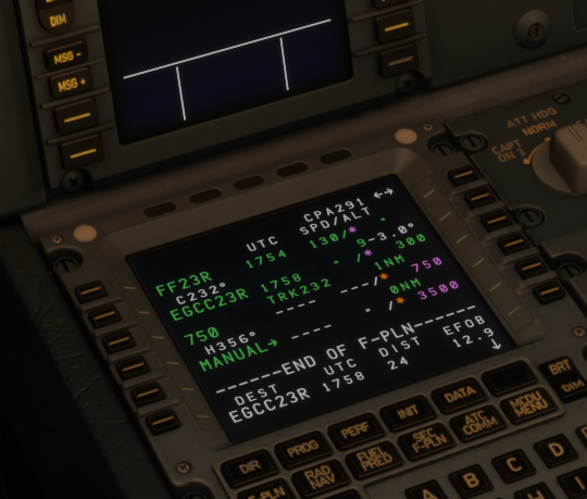
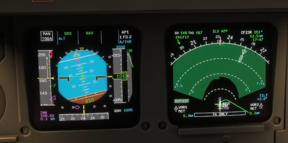
Ok we've checked, and in the navdata its only checking for 750ft before initiating the turn. There is no defined logic in the navdata itself to look for "750ft or D0.0 INN (D0.3 MCT) whichever is later" as charted. This would be an instance of pilot vigilance/checking required along with manual takeover in general. I have also attached my attempted missed approach, which clearly shows the aircraft maintaining runway track until passing 750ft, then initiating the turn after. The drawn 356 track is also visibly not starting from EGCC23R threshold (as if it were, it would have been much further right), but instead from computed VNAV path where 750ft would be satisfied. 2025-11-04 01-43-33.mp4 If you also look closely in the video, you'll also note we have essentially satisfied the D0.3 MCT during the turn anyways and it is all well within the margins. In your case, as soon as EGCC23R was sequenced, and 750ft satisfied (if you were above it already), then the track to 356 got drawn, which is why the both seemed to coincide. But anyways, as mentioned, there is no distance check in the navdata itself, hence the drawn path. Thanks!
-
Hi @ShermheadRyder Is this using Navigraph or Sim Default navdata?
-
Hi Please follow the above guide. Both the A340 and A350 use the same method (navigraph WASM module), for downloading/updating navdata via the EFB/OIS respectively. So there's no reason why it would work for one and not the other. You can try any of the following as troubleshooting steps: Log out then reconnect your navigraph via the EFB Close the sim, delete your Navigation data manually, then try to download again. FS24 Navdata Folder Paths- Steam: %APPDATA%\Microsoft Flight Simulator 2024\WASM\MSFS2024\inibuilds-aircraft-a340\work\NavigationData- MS Store: %LOCALAPPDATA%\Packages\Microsoft.Limitless_8wekyb3d8bbwe\LocalState\WASM\MSFS2024\inibuilds-aircraft-a340\work\NavigationData Try to use a VPN to another region to workaround any regional temporary server outages Yes its the same database. Thanks!
-
Thanks, logged.
-
Hi @Dolly64 Note that if you enter an overspeed condition, the FD will go off (by design). This can happen if any abrupt weather changes happen during your flight which cause drastic change in atmospheric conditions. In previous versions, when the overspeed condition was resolved, the FD were turning back on automatically, however per SME Feedback this was incorrect. This was one of the fixes in v1.0.2, so would explain why you are only *noticing* this in latest version, even though this issue may be occurring previously as well.
-
Thanks for your reports. As mentioned, we're investigating this matter, with your reports forwarded to MS/Asobo teams for perusal. However, as the WASM module isn't crashing, it is very difficult to reproduce or investigate this matter "quickly". We are hopeful a solution is found by the relevant parties soon. In the meanwhile, if you are experiencing this issue, please report with as much information as possible. Thanks!
-
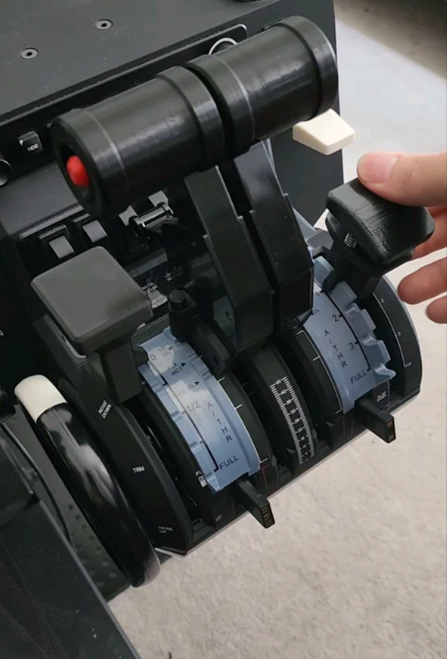
Hi @dennisko762 Are you still experiencing this issue? I am using Honeycomb Bravo TQ myself, with physical axis 3 set to ENG 1&2, and physical axis 4 set to ENG 3&4, using the airbus detents (though has not effect software wise). I am not able to reproduce your reported issue so was just curious if you could provide any additional information that could help with reproduction?
-
Hi @Blaster254 This is correctly modelled behaviour per the references made available by our SMEs. We have no reproduction of the issue. Checked across EIS1 and 2 variants, the dome light is working as intended across DIM, BRT and STORM positions. Its possible it may be happening due to an incomplete/improperly streamed assets? Can you confirm you're still having this issue now as of 1.0.2? 2025-11-03 20-10-16.mp4 Thanks!
-
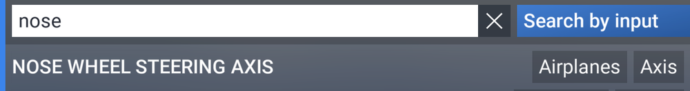
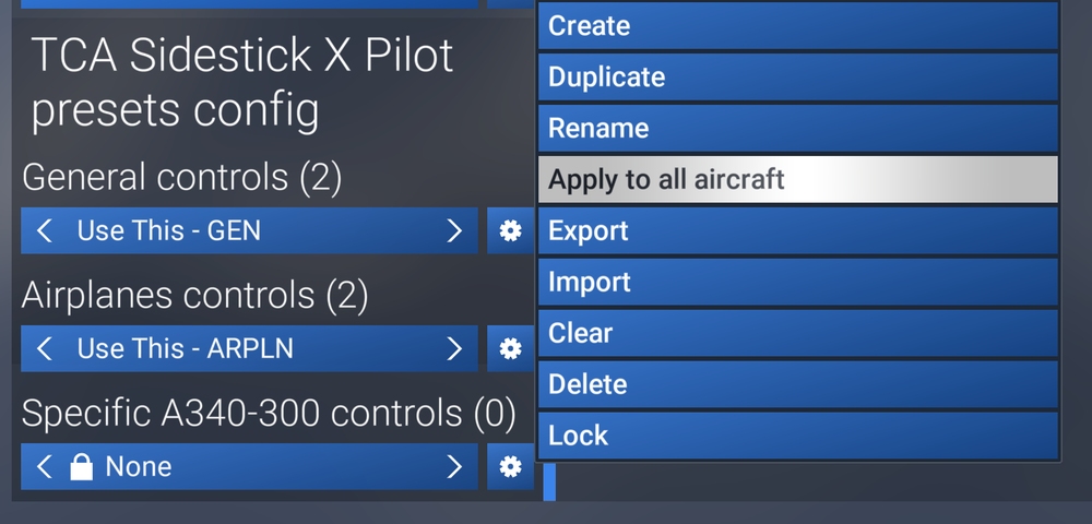
Hi, We do not have reproduction of any of your reported issues internally or amongst our testers once control profiles and controllers are properly configured. As for issues resolved after toggling GSX integration, sounds like GSX tugs are not properly releasing the aircraft, hence the difficulty with nosewheel steering and additional thrust required. Neither of those are normal conditions, and we are limited in how GSX behaves but things you should ensure Correct GSX profile installed (and properly in the right directory). The final path of the installed profile should be: You have completed the pushback procedure properly, with GSX having removed your gear pin and properly dismissed you. You need to wait for the marshaller to release you, starting taxi prematurely may have that effect. Ensure your chocks are properly removed prior to and after pushback. Chocks are controlled via the EFB Ground page. As for steering in general On the EFB Settings > Aircraft Settings page, there is a RUDDER CONTROLS TILLER option. When set to YES, your rudder axis controls the tiller as well. When set to NO, then the nosewheel has limited deflection, with full range of movement only possible via "Nose Wheel Steering Axis" in settings. Skidding is simulated with latest FS2024 ground handling physics, so you need to properly manage your speeds when initiating steep turns (less than 10kts GS). You also need to carefully use your rudder/tiller to steer into the turn, instead of slamming full LEFT/RIGHT to ensure proper turning. As for control profiles, since FS2024 has aircraft-specific control profiles now, ensure your correctly defined GENERAL, AIRPLANES and SPECIFIC A340-300 controls profiles are active. You may need to toggle between profiles or APPLY TO ALL (if you use the same across aircraft) for proper application. The same is true for any axis calibration/inversion applied. Thanks!
-
Hi @aekki From the dev team: Thanks!
-
The aircraft is already highly optimized, so I'm not sure what else can be done to meet that expectation? For context we have testers using it across a spectrum of hardware, from mid-tier 20-series cards all the way up to the latest high-end 50-series, not to mention the same aircraft is available for use on Xbox. So while we are open to suggestions, do note that no effort has been spared to optimize performance already - be it code or art side and the resultant product is the best that can be achieved based on current knowledge and sim conditions. I'm sure you're aware but for the benefit of anyone else reading this - some things you should take into account: Hardware: you do have to be mindful of your hardware in adjusting your sim settings, especially when running at high resolutions (like 4K) with many addons. Render Resolution, Texture Resolution, Object & Terrain LOD settings will have a huge impact on your experience. Especially when you set it at the edge of your hardware capability such that there is little headroom for the smallest overrun in certain conditions (e.g. larger amounts of ai traffic models spawned than anticipated). For 4K at native render res with TAA, at High Texture Resolution, Terrain & Object LODs above 120, in excess of 16GB VRAM is recommended. Anything less, you should adjust accordingly. Liveries or any texture modification packs: The official liveries on the iniManager (or marketplace livery packs) are using the decal-painting method that allows for dynamic-scaling depending on your distance from the aircraft all the while keeping texture resolutions to a bare minimum (less than 2K even). By comparison, many 3rd Party Liveries still use the traditional method of painting on model textures directly, then exporting at extremely high resolutions (8K/4K) which will cause VRAM usage to spike unnaturally so you should take that into consideration. This method is used throughout the aircraft texturing process, inside out, as well as strict adherence to node/bone limits on models, and extensive use of FS24 LODs system to achieve the performance this aircraft currently has. Thanks!
-
Hey Thanks for your report. I've forwarded to the team. In the meantime, have you tried reaching out to Wingflex support team? @Louis P Usually it is for the hardware makers to ensure their products are compatible with the existing sim software, and if not reach out to developers of those software for additional information/action required. Thanks!
-
Thanks for the update. Yes need to ensure the files downloaded from the link below are placed in the correct directory. The final path should look like as follows: Thanks!
-
Hi @2302rs Unfortunately, this isn't an actionable report for the reasons listed below: This doesn't appear to be an A340 WASM crash. In fact the enclosed screenshot shows an issue with the "noolaero" WASM module, which has nothing to do with the A340. Report also does not provide us with any information to try and reproduce what you experienced, to then be able to observe it with additional debugging tools attached to the sim to determine the cause. In case you are experiencing this issue again, make another report along with all requested information in the WASM Crash report guide. Thanks!
-
Hi everyone, It does work and has done so since launch, though not as consistently across the board for all users as we'd prefer. We have identified this to be a potential artefact related to MP streaming/compression and notified MS/Asobo accordingly. If any changes are required/implemented on our end, it will be noted in the changelog explicitly for that particular update. Thanks for your patience meanwhile. 2025-11-03 18-13-50.mp4
-
Hi, Please try to reach out to Microsoft Support via Zendesk for more information: https://flightsimulator.zendesk.com/hc/en-us/requests/new Perhaps they have a solution for you. Thanks!
-
Thanks for your feedback, it is logged for the team.
-
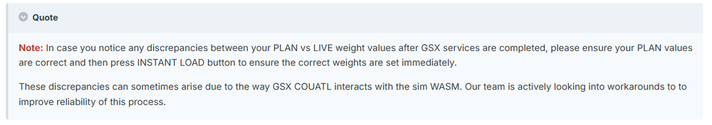
Hi, You can refer to this guide here: Also ensure you have the right GSX profile in as GSX lacks any "internal" profile for the aircraft and the values it identifies as default are rather incorrect. As for payload and fuelling, please refer to this note on the guide as well. Thanks!
-
Hi, That sounds like a potential driver or shader cache issue. I would recommend clearing your GPU Shader Cache if you haven't done so for a while. There are plenty of video guides online, such as this that can help. Use the appropriate method for your particular brand of GPU (AMD or Nvidia). Thanks!
-
Hi, full / official compatibility for WinWing MCDU is still on the way, and not yet the case as of A340 v1.0.2. Until that happens in a further update, the MCDU may not work 100% reliably. When full compatibility is available, it will be noted explicitly on the changelog and accompanying posts. Appreciate your patience in the meantime.
-
@wolfko That is precisely what the comment above was referring to, and it is indeed a sim limitation. Please re-read the comment above to understand. The "grass" around the roads is part of the sim's road/vector data overlay, which isn't taking the snowfall into account. The sim currently does not allow custom scenery to overwrite this sim vector data or layer above it.


