

richboy2307
-
Posts
1685 -
Joined
-
Last visited
-
Days Won
83
Content Type
Profiles
Forums
Downloads
Everything posted by richboy2307
-
That is just the nature of how the new sim handles pilot/character models for the time being. Not much we can do about it other than remove models completely (then it would be just hollow cockpit). Thanks!
-
Close the simulator if it is running. Navigate to your your FS24 WASM Folder: Steam: MS Store: Delete all the contents of this folder. This folder and its contents will be re-generated next time you load into a flight with the aircraft. Note: This will reset your EFB Throttle Calibration and EFB Settings so they should re-done the next time you load into the aircraft.
-
Hi @Roaring40s Please use the Weight & Balance app on the aircraft EFB for Fuel & Payload management on the A300. Same is applicable to the A310. Do NOT use the sim's Weight & Balance window for that. This window is not indicative of the actual fuel & payload logic of the aircraft, which should only be manipulated via the EFB Weight & Balance app. Thanks!
-
This is a known issue affecting HTML pages in the sim. Rest assured that we are investigating the issue and communicating with Asobo regularly to identify and implement a fix which will be pushed in a follow on update as soon as feasible. Thanks!
-
Please try with an empty community folder to rule out any addon conflicts. Thanks!
-
 The A300-600R Airliner, now available for MSFS2024 in two distinct versions. A300-600R Compatible Version (MSFS 2020 & MSFS 2024) - FREE for all previous owners A300-600R Premium Version (MSFS 2024 ONLY)- £9.99 (excl VAT) upgrade for all previous owners The Premium Edition takes advantage of MSFS2024’s advanced technology to offer a host of new features and improvements such as: Flight Model Updates Preflight Walkaround EFB Enhancements Performance & Structural Updates Sound Improvements For more information on these new features and improvements, see our announcement here: https://forum.inibuilds.com/topic/24363-lets-talk-inibuilds-a300-600r-airliner-updates-for-msfs2024-msfs2020/
 -
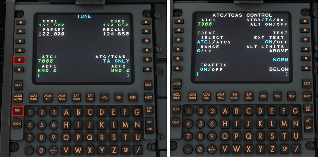
The Transponder and TCAS modes are switched via the ATC/TCAS CONTROL page of the IDC. To access this page, press TUN > LSK L5 on the ATC1 code. To set the Transponder Code (XPDR), use the numpad to enter the desired squawk code into the scratchpad, then press LSK L1 to enter it into the ATC1 field. To SQWK IDENT press LSK L2 when the active TCAS mode is TA/RA or ALT ON. It will flash dark grey/white when successful. To change the TCAS RANGE between 6nm and 12nm respectively, press LSK L4. The active value will be highlighted in blue. To enable/disable TRAFFIC display on TCAS, press LSK L6 to toggle ON or OFF. The active value will be highlighted in blue. To change the active TCAS MODE, press LSK R1 repeatedly to cycle between STBY, TA/, TA/RA, ALT ON, ALT OFF modes. The active value will be highlighted in blue. To run the TCAS TEST, press LSK R2. It will turn dark grey to indicate the test is active. It will return to white when complete. To run an extended TCAS test, press LSK R3 to toggle ON. Then press LSK R2 to run relevant test. To switch TCAS ALT LIMITS press LSK R4, R5 or R6 for ABOVE, NORM or BELOW modes respectively. For more information on IDC Operation and how to log-on to to the Hoppie Network, please see the linked video below:

-
Press the TUN button to access the TUNE page of the IDC where you can select the desired COM 1/2 frequencies, along with the ADF 1/2 frequencies. Simply use the number pad to type the desired frequency into the scratchpad (e.g 122.8). Then select the appropriate LSK (e.g. LSK L1 for COM 1 active frequency). You can swap between the STBY and ACTIVE frequency by pressing the RECALL LSK (e.g. LSK L2 for swapping COM1 standby frequency in white to the active frequency in green). To access the COM/ADF CONTROL page, ensure you have an empty scratch pad and then click the active COM/ADF frequency by selecting the appropriate LSK (e.g. LSK L1 for COM1 CONTROL page). Here you may define COM PRESETS by typing in the following format XXX.XXX/NAME (e.g. 121.5/GUARD) and then selecting the appropriate LSK (e.g. LSK L4 for COM PRESET #2). You may save up to 3 presets. To use a PRESET frequency, return to the TUN page and type into scratchpad PX (where X is the desired preset number, e.g. P2 for 121.500). The select the desired LSK (e.g. LSK L1 for Preset #2 of COM 1). For more information on IDC Operation and how to log-on to to the Hoppie Network, please see the linked video below:
-
The IDC is a modern retrofit pedestal which contains RMP units that allow for ACARS/CPDLC functionality via a screen. It can be enabled via the aircraft EFB Settings App (Cockpit Settings > IDC > SHOW) To use these functions, you must have an active Hoppie ACARS Log-on Code which you can obtain from their website: https://www.hoppie.nl/acars/system/register.html You can copy-paste your Log-On Code directly into the EFB Settings App (Third Party Settings > Hoppie) by using 'Cntrl+C' and 'Cntrl+V' commands. Alternatively you can type it in using your keyboard or the on-screen keyboard if enabled. For more information on IDC Operation and how to log-on to to the Hoppie Network, please see the linked video below:
-
There is an Electronic Flight Bag (EFB) located on either side of the cockpit (Captain and First Officer) which is intrinsically linked to the aircraft Flight Management System (FMS). It is also linked to some core simulator functions like setting your desired fuel and payload. Note: Please do not use the Microsoft Flight Simulator weight and balance menu/ universal EFB – this will have no impact, and may cause issues with your flight. Simply select the desired App to navigate the pages. Weight & Balance Page – This page allows you to set the fuel and load on the aircraft. You can set your fuel and payload manually by typing in the values into the text boxes. Alternatively, the (1) 'UPDATE FROM SIMBRIEF' button* allows you to import your planned fuel and payload directly from your OFP. Make sure to hit the (2) 'APPLY LOAD TO AIRCRAFT' button after to begin loading. You can complete the loading instantaneously by selecting the (3) red loading icon that appears at the top of the EFB. Hit the (4) 'FINISH NOW' button on the notification to do so. *Note: This feature only works after you have entered your Simbrief Pilot ID on the Settings page. Your Pilot ID is found on the 'Account Settings' page on Simbrief. Settings Page - Ensure your (5) Simbrief Pilot ID is entered on the EFB Third Party Settings. You can also switch (6) Weight Units between Metric (KG) and Imperial (LBS) units here.
-
Walkaround features such as being able to conduct a full preflight check by interacting with wear and tear areas, integrating MSFS2024's advanced wear system are only available in the Premium Edition of the A300-600R Airliner. For more information see: https://forum.inibuilds.com/topic/24363-lets-talk-inibuilds-a300-600r-airliner-updates-for-msfs2024-msfs2020/ In order to exit walkaround you must use the user-defined key bind for 'TAKE CONTROL OF CHARACTER' (Default: Shift+C). Control Settings - Keybind for Entering/Exiting 'Preflight' mode
-
You must calibrate your throttles via the aircraft EFB "Throttle Calibration" app. Firstly you must establish if you use reverse thrust on an axis or not. If no, ensure 'REVERSE ON AXIS' is set to NO on the EFB. You will have to bind reverse thrust to a button / input on your hardware. If yes, and you do intend on using reverse thrust on an axis, ensure you set this to YES. Then you may begin the calibration process by pressing 'START CALIBRATION' button. Move your hardware axis physically to its idle position then press the highlighted 'SET IDLE POSITION' button. Next, your hardware axis physically to its full forward position then press the highlighted 'SET TOGA POSITION' button. You will be greeted with a green bar on the top saying 'THROTTLE CALIBRATION IS SAVED' once completed. Note: Reload the plane to ensure this change is made properly.
-
This is normally done using the tiller located on the side console. The tiller can be controlled via the 'NOSE WHEEL STEERING AXIS' binding. For simulation purposes, this can also be linked to the rudder pedals for easier use. To do this, go to the aircraft EFB 'SETTINGS' app, then select 'YES' for the 'RUDDER CONTROLS TILLER' option.
-
If your aircraft is not following the flight path correctly, please check your MSFS Assistance settings and ensure that the 4 options highlighted below in red below are switched to OFF.
-
Your IRS must be aligned for these to remain latched. Switch all IRS switches to NAV on the overhead, and click ALIGN IRS in the FMS INIT A when your City Pair has been entered.
-
At least one Pitch Trim switch must be on for them to illuminate. Note: The pitch trim switch will only remain on once IRS has been aligned.
-
The Thrust Rating Panel (TRP) immediately to the right of the engine instruments is used for thrust rating control. To set a Flex temp, click the FLX.TO button, then use the dial next to it to dial in your Flex temp.
-
Press the red button on the left of the yoke to cancel the sound.
-
We have numerous support tools on this product: 1. The manual 2. The Welcome to the A300-600 video A300_MSFS_Manual.pdf
-
Creating a custom background instructions Use the addon template Replace the images (freight.png and pax.png) as desired in the html_ui\Pages\VCockpit\Instruments\ini-common folder of the addon You should now have your own customised background! inibuilds-a300-efb-classicbackground.zip
-
Known Issues Under Investigation The MSFS2024 A300-600R Compatible Edition, is being initially released in a Beta state. While the product is functional we've identified a few areas that require further refinement before we identify it as fully compatible: Terrain Display Loss of overhead Korry switch and ambient packs/bleed sounds when switching views Random TCAS RA errors from own plane Networking issue highlighted in greater detail below We appreciate your understanding and ask that if you do experience any issues/find any solutions, please do let us know on the iniBuilds Forum here, so that we may resolve these issues ASAP. Freezing on End Flight / Return to Menu We have discovered a current core sim issue relating to networking that prevents users from fully closing the simulator after completion of a flight. While this does not affect anything related to loading or using the aircraft either offline or with Multiplayer/Online networks, you will not be able to return to the menu UI without closing the simulator process via the task manager. Rest assured that we are investigating the issue and communicating with Asobo regularly to identify and implement a fix which will be pushed in a follow on update as soon as feasible. EFB Enroute Map Flicker Currently, there is a known core bug with the way js maps are read by the sim. The mapping client we and many other developers use (leaflet) is not currently compatible with the sim SDK. While we and Asobo work towards a solution, it's best to either avoid using the Enroute Map or understand it will flicker at times. (We have found the flickering does begin to subside after a few minutes over the duration of a flight) Liveries New 'MSFS2024 Premium Edition' liveries are not compatible with the MSFS 2020/2024 Compatible version due to the new file structure. You may use any 'MSFS 2020' A300 liveries with the MSFS 2020/2024 Compatible edition downloaded via the iniManager. Core Sim Known Issues & Considerations While the title is jam-packed with countless new and improved features, we also want to keep you informed about some current issues that may affect your experience as a whole. The below is a non-exhaustive list of things to look out for while the platform grows and evolves to full maturity:
-
iniBuilds A300-600R GE Airliner Passenger Variant: https://dispatch.simbrief.com/airframes/share/347385_1702657155316 iniBuilds A300-600RF GE Airliner Freighter Variant: https://dispatch.simbrief.com/airframes/share/347385_1703262262270 iniBuilds A300-600R PW Airliner Freighter Variant: https://dispatch.simbrief.com/airframes/share/347385_1711122593284 iniBuilds A300-600R PW Airliner Passenger Variant: https://dispatch.simbrief.com/airframes/share/347385_1711546435461
-
- 1
-

-
The Transponder and TCAS modes are switched via the ATC/TCAS CONTROL page of the IDC. To access this page, press TUN > LSK L5 on the ATC1 code. To set the Transponder Code (XPDR), use the numpad to enter the desired squawk code into the scratchpad, then press LSK L1 to enter it into the ATC1 field. To SQWK IDENT press LSK L2 when the active TCAS mode is TA/RA or ALT ON. It will flash dark grey/white when successful. To change the TCAS RANGE between 6nm and 12nm respectively, press LSK L4. The active value will be highlighted in blue. To enable/disable TRAFFIC display on TCAS, press LSK L6 to toggle ON or OFF. The active value will be highlighted in blue. To change the active TCAS MODE, press LSK R1 repeatedly to cycle between STBY, TA/, TA/RA, ALT ON, ALT OFF modes. The active value will be highlighted in blue. To run the TCAS TEST, press LSK R2. It will turn dark grey to indicate the test is active. It will return to white when complete. To run an extended TCAS test, press LSK R3 to toggle ON. Then press LSK R2 to run relevant test. To switch TCAS ALT LIMITS press LSK R4, R5 or R6 for ABOVE, NORM or BELOW modes respectively. For more information on IDC Operation and how to log-on to to the Hoppie Network, please see the linked video below:
-
Press the TUN button to access the TUNE page of the IDC where you can select the desired COM 1/2 frequencies, along with the ADF 1/2 frequencies. Simply use the number pad to type the desired frequency into the scratchpad (e.g 122.8). Then select the appropriate LSK (e.g. LSK L1 for COM 1 active frequency). You can swap between the STBY and ACTIVE frequency by pressing the RECALL LSK (e.g. LSK L2 for swapping COM1 standby frequency in white to the active frequency in green). To access the COM/ADF CONTROL page, ensure you have an empty scratch pad and then click the active COM/ADF frequency by selecting the appropriate LSK (e.g. LSK L1 for COM1 CONTROL page). Here you may define COM PRESETS by typing in the following format XXX.XXX/NAME (e.g. 121.5/GUARD) and then selecting the appropriate LSK (e.g. LSK L4 for COM PRESET #2). You may save up to 3 presets. To use a PRESET frequency, return to the TUN page and type into scratchpad PX (where X is the desired preset number, e.g. P2 for 121.500). The select the desired LSK (e.g. LSK L1 for Preset #2 of COM 1). For more information on IDC Operation and how to log-on to to the Hoppie Network, please see the linked video below: