


richboy2307
Staff
-
Joined
-
Last visited
Everything posted by richboy2307
-
Thanks the issue with reversed order of wind input is known and reported.
-
Hi, Please allow some time for response as the team is not usually working over the weekends. The custom effect we used for wiper & raindrop animation in MSFS2020 does not function in MSFS2024. This is a known issue and the team is actively looking into possible solutions/workarounds. Thanks!
-
The engine cowlings can be opened on the GE Engines only (Pax or Freighter). You must remove the covers first (Aircraft EFB > Ground Equipment Page), and then you can open/close the cowlings via either of these ways: Walkaround Mode: Left Click the clickspot on the cowling itself for each engine. Aircraft EFB: Select the 'Aircraft Maintenance' app to access the Engine Cowling and other maintenance options. Thanks!
-
-
Hi @gvert This is unfortunately an issue caused either due to incomplete WASM compilation or improperly streamed package. Firstly, try the debugging steps with the ThrottleData.ini file mentioned in this post: In your case, you want to see the following on your ThrottleData.ini file: You may also try to delete the the A321 WASM folder and force a re-download of the package using below guides: Thanks!
-
Hi @Mammer Is the issue only happening on the replay? I would check and remove any control bindings related to "Mixture" (axis or buttons). Also please disable the AI Assists mentioned here:
-
Hi, Merged topics as similar discussion. You can read the statement again: Keyword here being independently. That documentation is pertaining to adding the sim's EFB in its entirety (as is) into a 3D model/display. What Navigraph is doing is adding pages within EFB panel itself. These are not the same things. These do not allow for integration of individual elements/functions for a seamless experience outside of the "stock" systems environment. As mentioned in the previous post, the best way forward is still the same: We're not saying it can never be done. We're not saying we won't do it. All we're saying is that the decision (be it for capability in the SDK or to add such integration on Microsoft Airbus aircraft) is not ours to make, so please make your requests/feedback known in the appropriate channels. Thanks!
-
Thanks reported and acknowledged same on discord. For now you may get around this by selecting another approach first, hitting ERASE then try again this time selecting the desired APPROACH and STAR. 2024-12-09_16-31-52.mp4 Thanks!
-
Can you please share the Simbrief OFP (PDF) of your planned flight? So we can try to reproduce the issue on our end and investigate the cause. Thanks!
-
There are limitations to the aerodynamic modelling of the string within MSFS 2020. Users do have the option to remove it via the EFB if they prefer. With regards to the bug, noted thanks!
-
Summary of Fuel System The fuel is normally fed to the engine via the FUSE tank. This tank can be topped up by transferring fuel from any of the 3 types of AUX tanks (TIP, L.E and WING) via their associated fuel tank switches on the left hand side of the cockpit. The fuel is transferred at an accelerated rate from the AUX tanks to the FUSE tank until it is full, and then the rate of transfer slows down to the rate of burn by the engine. Fuel DOES NOT start to vent simply when the FUSE tank is full. When does the fuel start to vent? The fuel begins to vent overboard only when both these conditions are satisfied The FUSE tank is full; and All AUX tanks (TIP, L.E and WING) are turned ON at the same time. This will be indicated by a FUEL VENT light on the main panel, just behind the control stick. These points are also illustrated via the video below: 2024-09-09 15-31-40(1).mp4 Thanks!
-
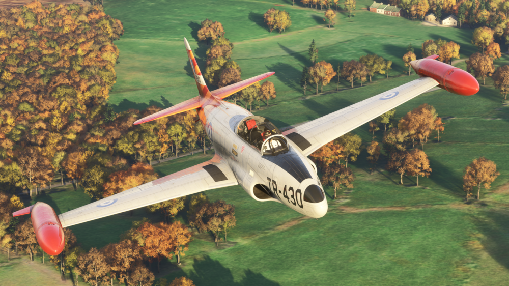
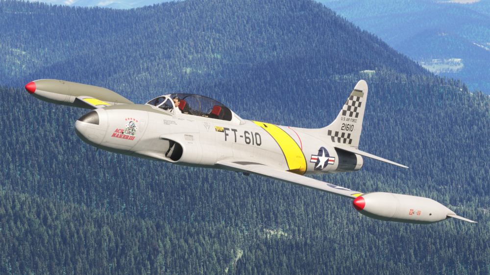
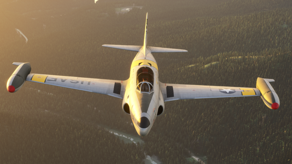
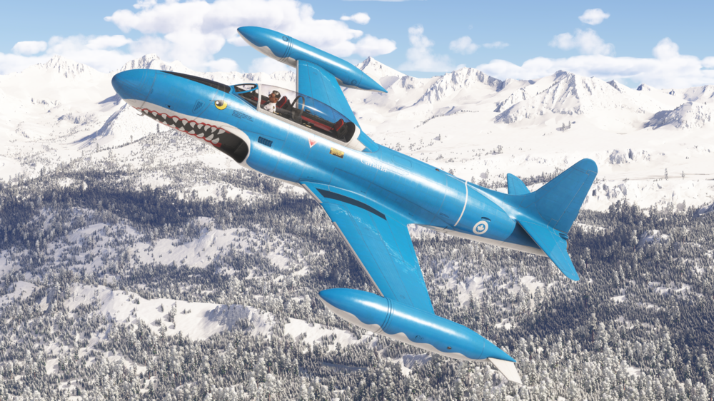
Getting ready to fly the iniBuilds T-33 Jet Trainer for the first time? Get ahead and learn the bits you need before you jump into the cockpit with our handy manual and QRC! T-33 MSFS2024 Manual & QRC - v1.0.4 (30th Nov 24) T-33_FS24_Manual.pdf T-33_QRC.pdf
-
Hello everyone! 👋 Today, we're excited to talk about our latest update to the T-33 Jet Trainer 🚀, which now fully supports Microsoft Flight Simulator 2024 (MSFS24) standards! If you haven’t had a chance to check out this iconic aircraft, now’s the time! With this new update, we’ve brought significant improvements to both the systems and visuals to align with the latest MSFS24 tech. You can click the link below to grab your copy, and with these changes, we’re confident you’ll love the new level of immersion! This is a free upgrade for previous owners! BUY HERE - £19.99 (excl VAT.) We’ve listened closely to your feedback, and the overall response to the T-33 has been overwhelmingly positive! 🙌 We’re thrilled you’ve enjoyed this unique addition to our line-up, and we’re even more excited to bring you this MSFS24 update. Let’s dive into the new features and refinements we’ve made, elevating the T-33 to meet the enhanced capabilities of MSFS24! MSFS24 Conversion and Features With the release of MSFS24, we’ve implemented several key features to fully utilize the platform’s advancements, ensuring a more realistic and dynamic experience for the T-33. Let’s take a look at what’s new: New MSFS24 Interaction Points: We've integrated MSFS24 interaction points for multiple systems across the aircraft. Now, you’ll find detailed interaction for items like covers, chocks, pins, and pitot covers, all tied into real-world dependencies. Forgetting to remove the engine cover? Your engine won’t start! Left the chocks on? You won’t be able to move! And don’t forget about the pitot cover, as it will cause incorrect airspeed readings if not removed. ✈️ Primary Flight Control Surfaces: In MSFS24, we've also introduced interaction points for primary flight control surfaces and landing gears, bringing enhanced realism to how you interact with the aircraft. This update also includes wear and tear for career mode, so you’ll notice changes over time that reflect your usage. Enhanced Lighting Effects: Both internal and external lighting effects have been enhanced to meet MSFS24’s lighting standards. Whether you’re on a night mission or flying through dawn, the lighting has been reworked to create a more dynamic and immersive experience. Visual and Texture Improvements In this update, we’ve taken the opportunity to bring the internal and external textures up to MSFS24 standards. From cockpit details to exterior liveries, everything has been converted to provide the most immersive and visually stunning experience possible. 🎨 We’ve also updated the checklist for the new MSFS24 EFB (Electronic Flight Bag) system, ensuring you have all the information at your fingertips, and this update ties into the visual and system improvements seamlessly. System and Flight Model Updates We’ve upgraded the sounds of the T-33 to MSFS24 standards, bringing a richer and more realistic sound profile to your flights. You’ll notice improved audio quality in both internal and external views. Cockpit Enhancements: We’ve made some modern cockpit improvements, including enhanced digital screen performance for a smoother, more efficient experience, especially on high-demand platforms like Xbox. Additionally, the in-cockpit EFB has been updated to handle MSFS24’s enhanced feature set. Thank you for your continued feedback and support! We’re excited for you to experience the T-33 in MSFS24, and as always, we’re eager to hear your thoughts on this latest update. Happy flying! 🛩️ ------------------------------------------ Changelog v1.0.4 - Conversion of the aircraft to FS24 standards including art, systems and FM. - New FS24 interaction points for covers, chocks, pins and pitot cover with dependencies. - If engine cover is on - the engine won't start, chocks not removed - you can't move forward, don't remove the pitot cover your airspeed will read incorrectly, plus more! - New FS24 interaction points for all primary flight control surfaces and landing gears including wear and tear for career mode. - New FS24 Modular file structure for improved visual performance on PC and Xbox with updated LODs. - Internal and External lighting effects enhanced for FS24. - Internal and external textures converted to FS24 standards. - Checklist updated for the new FS24 EFB. - Improved sounds to FS24 standards. - In-cockpit EFB updated. - Modern cockpit digital screens improved for performance. - Flight manual updated for new FS24 features.
-
That is just the nature of how the new sim handles pilot/character models for the time being. Not much we can do about it other than remove models completely (then it would be just hollow cockpit). Thanks!
-
Close the simulator if it is running. Navigate to your your FS24 WASM Folder: Steam: MS Store: Delete all the contents of this folder. This folder and its contents will be re-generated next time you load into a flight with the aircraft. Note: This will reset your EFB Throttle Calibration and EFB Settings so they should re-done the next time you load into the aircraft.
-
Hi @Roaring40s Please use the Weight & Balance app on the aircraft EFB for Fuel & Payload management on the A300. Same is applicable to the A310. Do NOT use the sim's Weight & Balance window for that. This window is not indicative of the actual fuel & payload logic of the aircraft, which should only be manipulated via the EFB Weight & Balance app. Thanks!
-
This is a known issue affecting HTML pages in the sim. Rest assured that we are investigating the issue and communicating with Asobo regularly to identify and implement a fix which will be pushed in a follow on update as soon as feasible. Thanks!
-
Please try with an empty community folder to rule out any addon conflicts. Thanks!
-
The A300-600R Airliner, now available for MSFS2024 in two distinct versions. A300-600R Compatible Version (MSFS 2020 & MSFS 2024) - FREE for all previous owners A300-600R Premium Version (MSFS 2024 ONLY)- £9.99 (excl VAT) upgrade for all previous owners The Premium Edition takes advantage of MSFS2024’s advanced technology to offer a host of new features and improvements such as: Flight Model Updates Preflight Walkaround EFB Enhancements Performance & Structural Updates Sound Improvements For more information on these new features and improvements, see our announcement here: https://forum.inibuilds.com/topic/24363-lets-talk-inibuilds-a300-600r-airliner-updates-for-msfs2024-msfs2020/
-
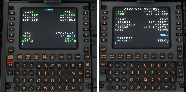
The Transponder and TCAS modes are switched via the ATC/TCAS CONTROL page of the IDC. To access this page, press TUN > LSK L5 on the ATC1 code. To set the Transponder Code (XPDR), use the numpad to enter the desired squawk code into the scratchpad, then press LSK L1 to enter it into the ATC1 field. To SQWK IDENT press LSK L2 when the active TCAS mode is TA/RA or ALT ON. It will flash dark grey/white when successful. To change the TCAS RANGE between 6nm and 12nm respectively, press LSK L4. The active value will be highlighted in blue. To enable/disable TRAFFIC display on TCAS, press LSK L6 to toggle ON or OFF. The active value will be highlighted in blue. To change the active TCAS MODE, press LSK R1 repeatedly to cycle between STBY, TA/, TA/RA, ALT ON, ALT OFF modes. The active value will be highlighted in blue. To run the TCAS TEST, press LSK R2. It will turn dark grey to indicate the test is active. It will return to white when complete. To run an extended TCAS test, press LSK R3 to toggle ON. Then press LSK R2 to run relevant test. To switch TCAS ALT LIMITS press LSK R4, R5 or R6 for ABOVE, NORM or BELOW modes respectively. For more information on IDC Operation and how to log-on to to the Hoppie Network, please see the linked video below:
-
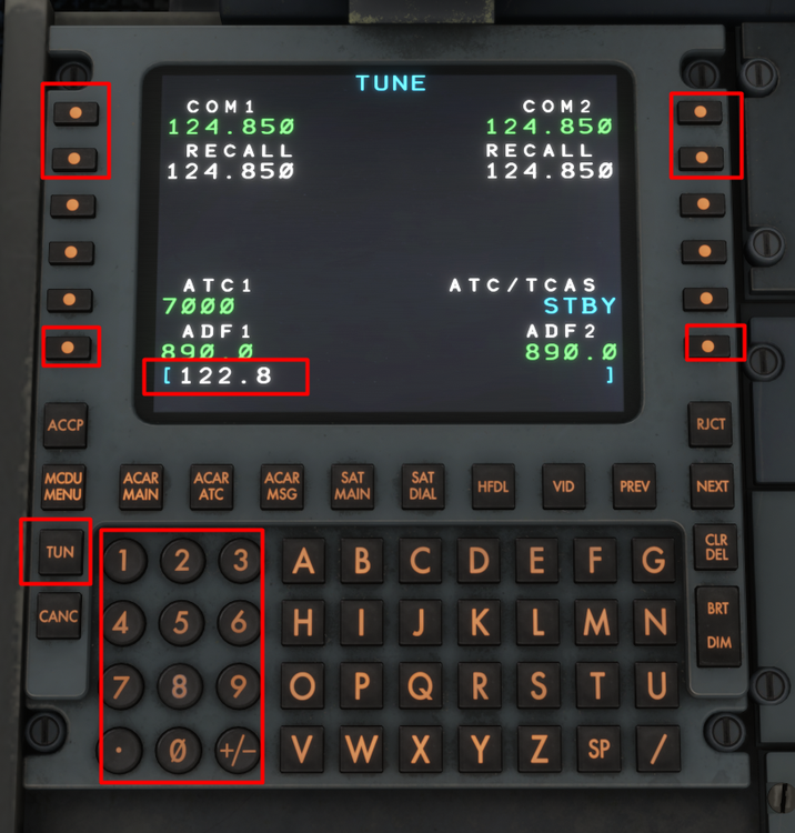
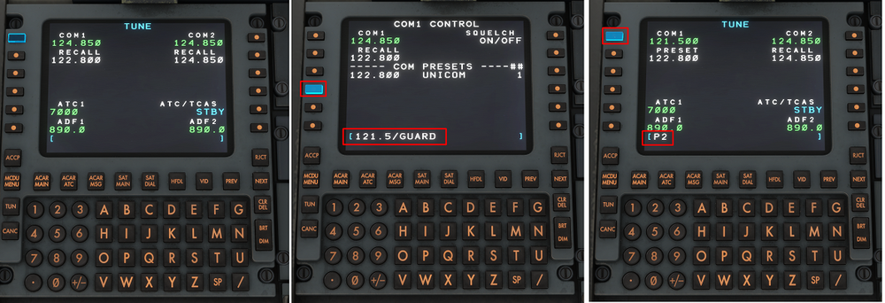
Press the TUN button to access the TUNE page of the IDC where you can select the desired COM 1/2 frequencies, along with the ADF 1/2 frequencies. Simply use the number pad to type the desired frequency into the scratchpad (e.g 122.8). Then select the appropriate LSK (e.g. LSK L1 for COM 1 active frequency). You can swap between the STBY and ACTIVE frequency by pressing the RECALL LSK (e.g. LSK L2 for swapping COM1 standby frequency in white to the active frequency in green). To access the COM/ADF CONTROL page, ensure you have an empty scratch pad and then click the active COM/ADF frequency by selecting the appropriate LSK (e.g. LSK L1 for COM1 CONTROL page). Here you may define COM PRESETS by typing in the following format XXX.XXX/NAME (e.g. 121.5/GUARD) and then selecting the appropriate LSK (e.g. LSK L4 for COM PRESET #2). You may save up to 3 presets. To use a PRESET frequency, return to the TUN page and type into scratchpad PX (where X is the desired preset number, e.g. P2 for 121.500). The select the desired LSK (e.g. LSK L1 for Preset #2 of COM 1). For more information on IDC Operation and how to log-on to to the Hoppie Network, please see the linked video below:
-
The IDC is a modern retrofit pedestal which contains RMP units that allow for ACARS/CPDLC functionality via a screen. It can be enabled via the aircraft EFB Settings App (Cockpit Settings > IDC > SHOW) To use these functions, you must have an active Hoppie ACARS Log-on Code which you can obtain from their website: https://www.hoppie.nl/acars/system/register.html You can copy-paste your Log-On Code directly into the EFB Settings App (Third Party Settings > Hoppie) by using 'Cntrl+C' and 'Cntrl+V' commands. Alternatively you can type it in using your keyboard or the on-screen keyboard if enabled. For more information on IDC Operation and how to log-on to to the Hoppie Network, please see the linked video below:


-
There is an Electronic Flight Bag (EFB) located on either side of the cockpit (Captain and First Officer) which is intrinsically linked to the aircraft Flight Management System (FMS). It is also linked to some core simulator functions like setting your desired fuel and payload. Note: Please do not use the Microsoft Flight Simulator weight and balance menu/ universal EFB – this will have no impact, and may cause issues with your flight. Simply select the desired App to navigate the pages. Weight & Balance Page – This page allows you to set the fuel and load on the aircraft. You can set your fuel and payload manually by typing in the values into the text boxes. Alternatively, the (1) 'UPDATE FROM SIMBRIEF' button* allows you to import your planned fuel and payload directly from your OFP. Make sure to hit the (2) 'APPLY LOAD TO AIRCRAFT' button after to begin loading. You can complete the loading instantaneously by selecting the (3) red loading icon that appears at the top of the EFB. Hit the (4) 'FINISH NOW' button on the notification to do so. *Note: This feature only works after you have entered your Simbrief Pilot ID on the Settings page. Your Pilot ID is found on the 'Account Settings' page on Simbrief. Settings Page - Ensure your (5) Simbrief Pilot ID is entered on the EFB Third Party Settings. You can also switch (6) Weight Units between Metric (KG) and Imperial (LBS) units here.


-
Walkaround features such as being able to conduct a full preflight check by interacting with wear and tear areas, integrating MSFS2024's advanced wear system are only available in the Premium Edition of the A300-600R Airliner. For more information see: https://forum.inibuilds.com/topic/24363-lets-talk-inibuilds-a300-600r-airliner-updates-for-msfs2024-msfs2020/ In order to exit walkaround you must use the user-defined key bind for 'TAKE CONTROL OF CHARACTER' (Default: Shift+C). Control Settings - Keybind for Entering/Exiting 'Preflight' mode


