




richboy2307
Staff
-
Joined
-
Last visited
Everything posted by richboy2307
-
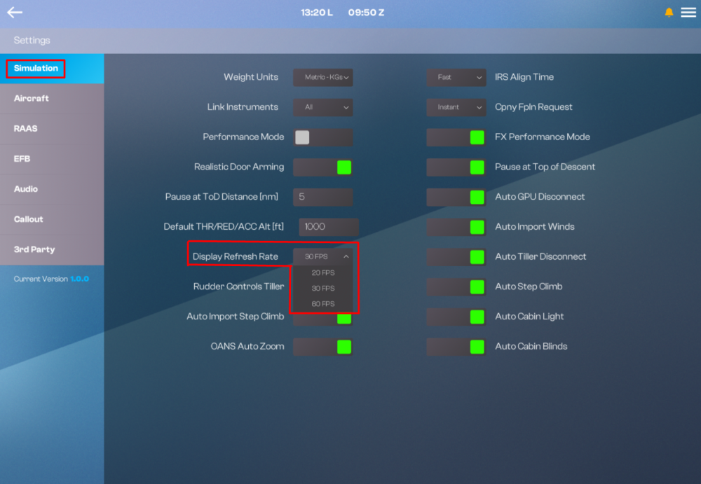
Changing the Display Refresh Rate on your iniBuilds A380 Airliner helps your simulator performance and stability by adjusting how frequently the aircraft's system displays and cursor update on CPU-limited systems. (Click to enlarge image) How to Change the Display Refresh RateNavigate to Settings: Select Settings from the home page Select the Simulation Page: From the left-hand sidebar, choose Simulation. Locate Display Refresh Rate: Find the Display Refresh Rate drop-down selector in the settings list. Choose Your Preferred Rate: Click the drop-down and select from the three available options: 20 FPS - CPU-limited systems experiencing stutters or frame drops, where maximizing performance is the priority. 30 FPS - A balanced middle ground - moderate performance gains with minimal impact on display smoothness. 60 FPS - Systems with strong single-core CPU performance, prioritizing the smoothest possible display updates. Changes take effect immediately, no restart is required.
-
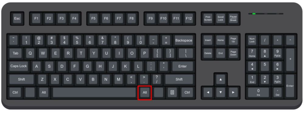
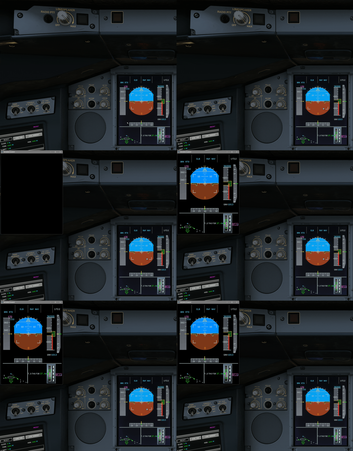
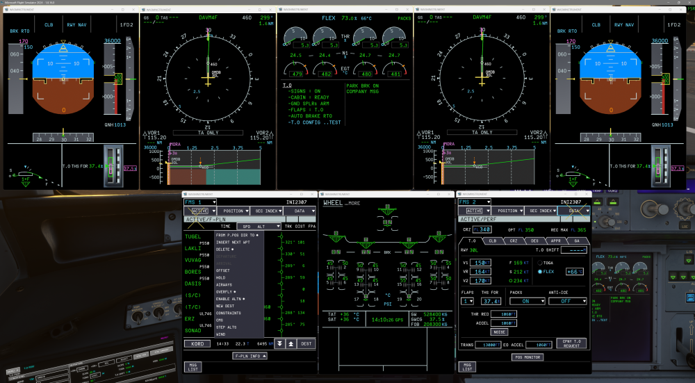
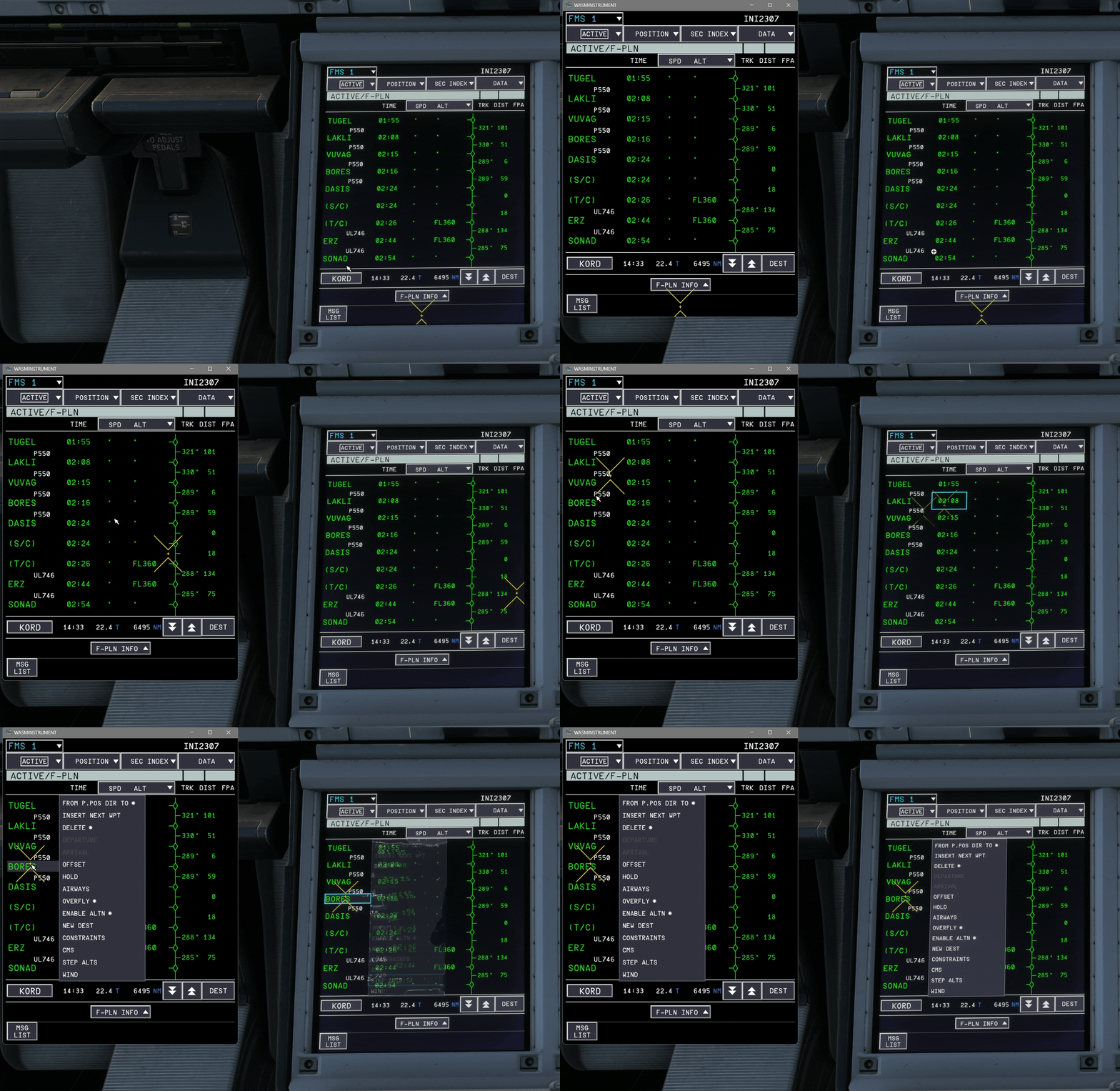
By popular demand, the iniBuilds A380 supports individual pop-out displays for the MFDs, EFB, and OIT screens. Each popped-out display remains fully interactive, allowing you to click, scroll, and operate them just as you would in the main cockpit view - perfect for multi-monitor or home cockpit setups. (Click to enlarge image) How to Pop-out a Screen?To pop out displays in MSFS 2024, hold the Right Alt key (or AltGr) and left-click directly on the center of any supported glass cockpit screen. (Click to enlarge image) The instrument opens in a separate, movable window that you can drag to a second monitor or resize. (Click to enlarge image)
-
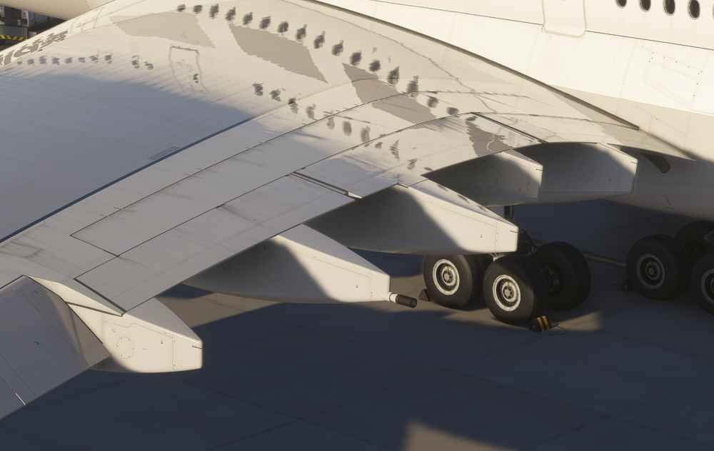
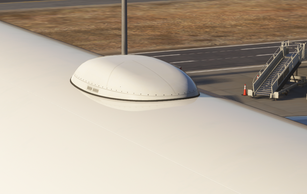
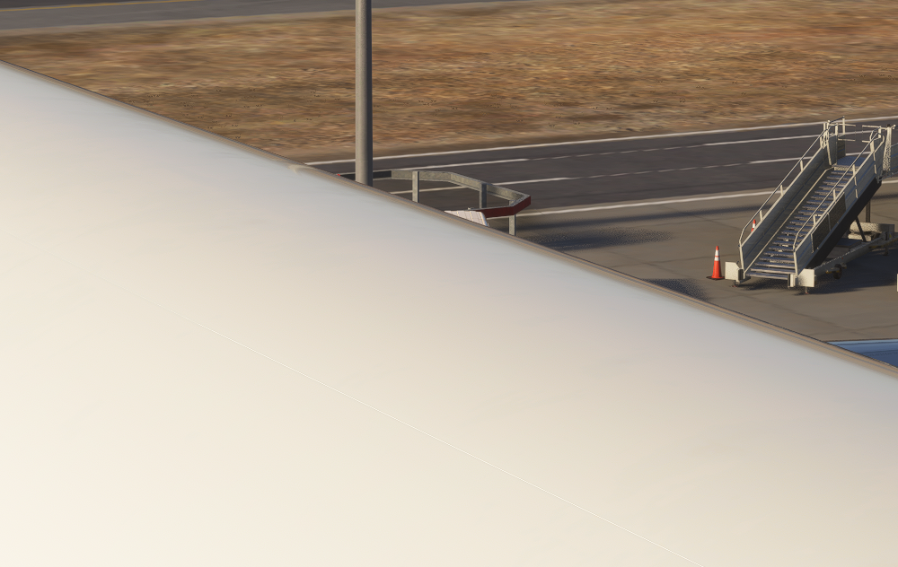
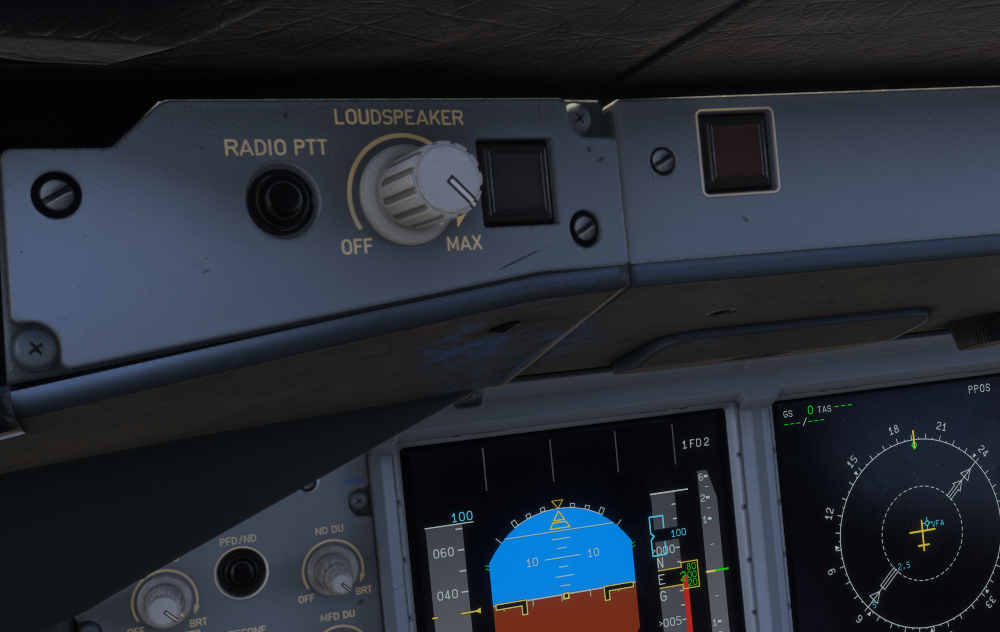
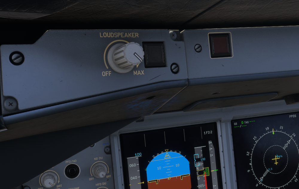
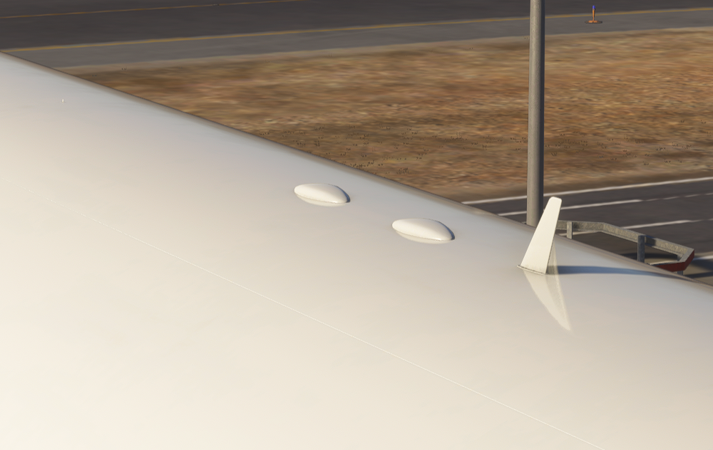
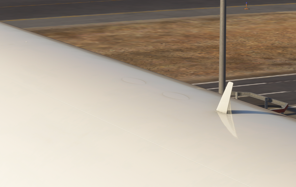
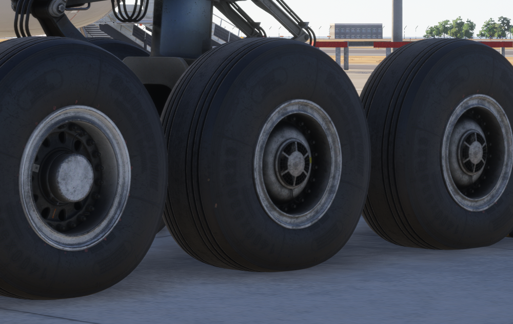
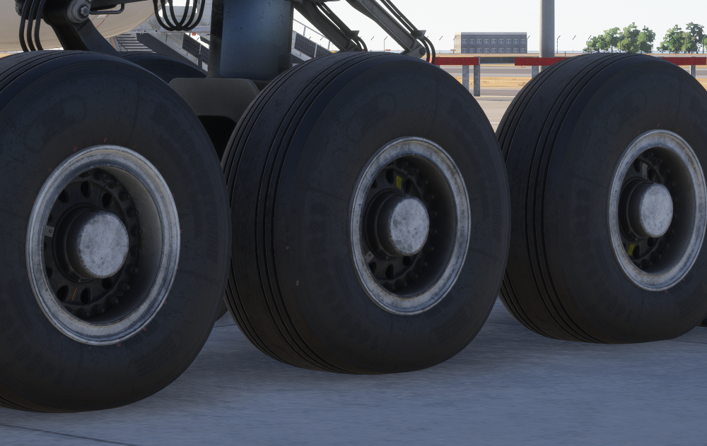
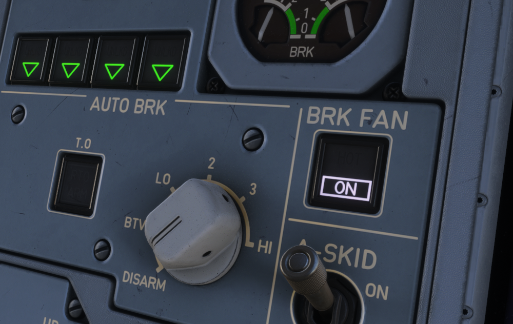
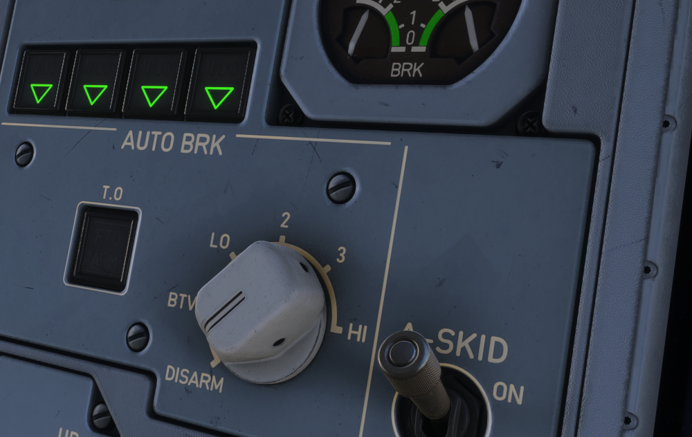
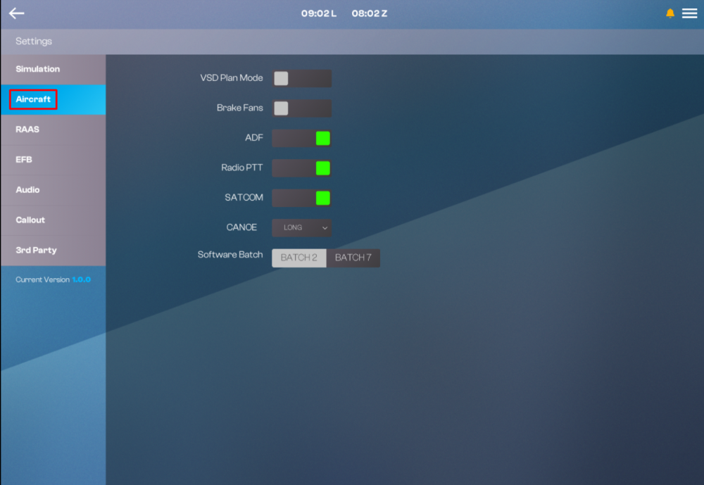
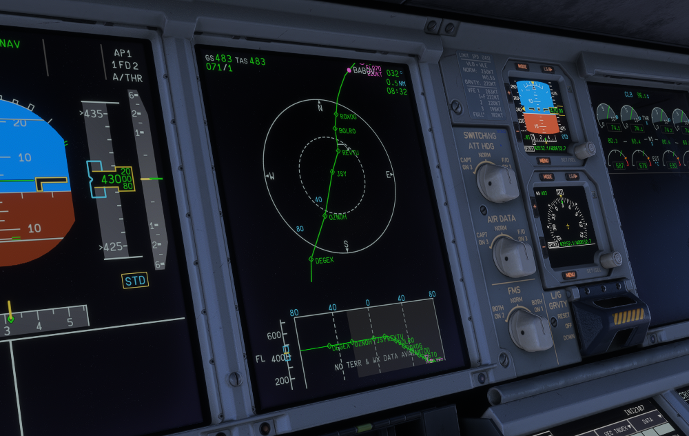
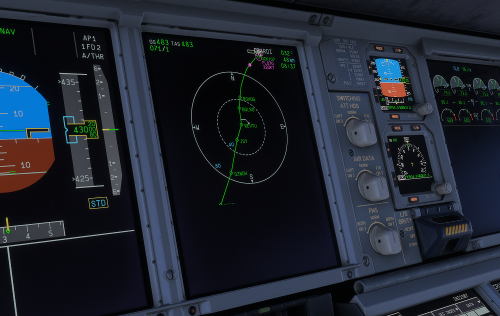
Customize your A380 to match your preferred operator configuration, from software batch selection to optional hardware equipment and airframe variations. All of these settings can be found on the EFB. How to AccessOpen the EFB home page. Select Settings. Choose the Aircraft tab from the left-hand sidebar. (Click to enlarge image) Equipment OptionsVSD Plan ModeToggle to enable or disable Vertical Situation Display Plan Mode functionality when the ND is in Plan Mode. (Click to enlarge image) Software BatchSelect between BATCH 2 or BATCH 7 software standards to match your preferred operator or era-specific configuration. Each configuration changes more than a handful of labels, introducing the appropriate FMS capabilities, flight-guidance logic, display behaviour, protections, procedures and checklist philosophy. The comparison below highlights some of the key differences between these two configurations and how the flight deck has evolved over time. (Click to enlarge image) RAASRunway Awareness and Advisory System (RAAS) settings are managed via their own dedicated tab. For more information see How to - RAAS - Setup and Operation. Brake FansToggle to enable or disable the presence of Brake Fans equipment on the aircraft and relevant cockpit switches and ECAM Memos and alerts. (Click to enlarge image) ADFToggle to enable or disable Automatic Direction Finder (ADF) equipment. (Click to enlarge image) Radio PTTToggle to enable or disable the Radio Push-To-Talk equipment on the glareshield for both pilots (visual only). (Click to enlarge image) SATCOMToggle to enable or disable Satellite Communications equipment at the top of the fuselage (visual only). (Click to enlarge image) CANOESelect between LONG or SHORT Outer Flap Track Fairing variants via the drop-down selector. This is a purely visual/external modelling option, allowing you to match your aircraft's fairings to a specific real-world airframe or operator preference. (Click to enlarge image)

-
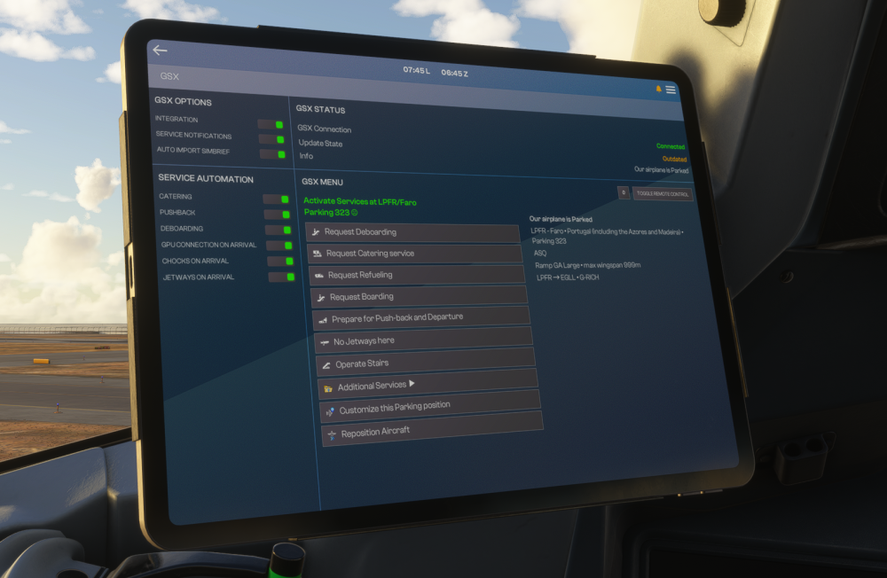
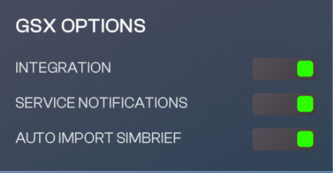
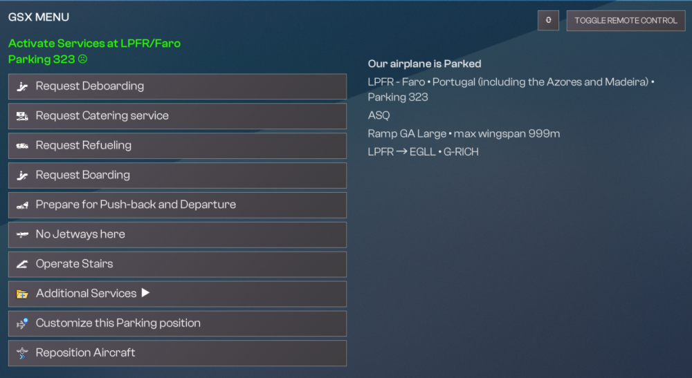
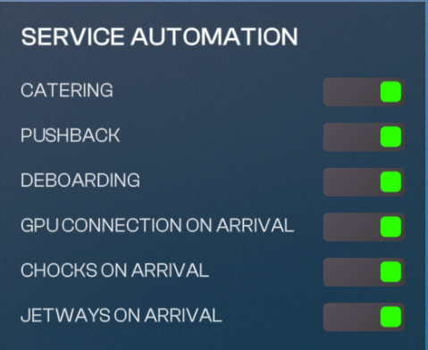
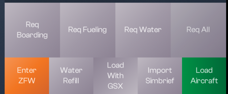
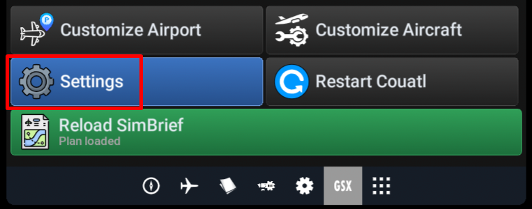
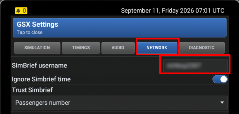
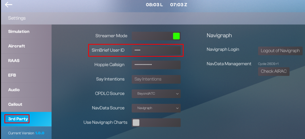
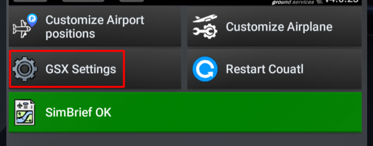
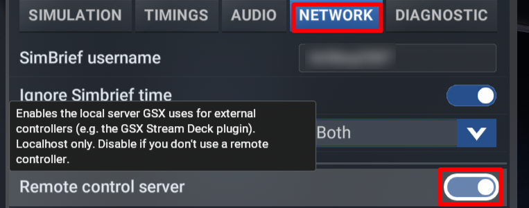
The iniBuilds A380 Airliner offers customizable GSX integration through the Electronic Flight Bag (EFB), enabling you to control and set the level of service automation provided by GSX. (Click to enlarge image) Pre-RequisitesDownload the official GSX profile here. Add your Simbrief User ID (numbers only) on the EFB 3rd Party Settings Page (Click to enlarge image) Add your Simbrief User ID (username) within the settings of GSX itself. (Click to enlarge image) Enable Remote Control Server within settings of GSX Itself. Note: this option is only available on the toolbar GSX Settings. It will not show on the EFB GSX settings. (Click to enlarge image) Setup - GSX Options PageThe EFB GSX Options page allows you to enable integration, service notifications as well as manipulate the GSX menu and setup the desired level of service automations. We will go over the functionality of each of the options on this page below. GSX STATUS GSX CONNECTION: Shows EFB connection status to GSX UPDATE STATE: Shows OUTDATED when a new GSX version is available for download. INFO: Shows current status of GSX Vehicles (Click to enlarge image) GSX OPTIONS INTEGRATION: Toggles GSX Integration & Remote Menu for access within the EFB SERVICE NOTIFICATIONS: Toggles the visibility of GSX notifications at the top of the EFB display AUTO IMPORT SIMBRIEF: Toggles the automatic import of your latest Simbrief OFP Data for GSX Loading Note: Requires you to enter your Simbrief User ID in GSX Settings as well as on the EFB 3rd Party Settings. (Click to enlarge image) GSX MENU TOGGLE REMOTE CONTROL : Toggles the visibility of GSX Remote menu as long as the INTEGRATION is set to ON. REFRESH: Refreshes the Remote Control page status. REMOTE MENU: Shows GSX action items. (Click to enlarge image) SERVICE AUTOMATION CATERING: Toggles automatic request of Catering services when using LOAD WITH GSX on the EFB Ground Operations - Weight & Balance page. PUSHBACK: Toggles automatic request of Pushback services when using LOAD WITH GSX on the EFB Ground Operations - Weight & Balance page. DEBOARDING: Toggles automatic request of Deboarding on shutdown (Engines Off, Brakes Set). GPU CONNECTION ON ARRIVAL: Toggles automatic GPU request on shutdown (Engines Off, Brakes Set). CHOCKS ON ARRIVAL: Toggles automatic Chocks request on shutdown (Engines Off, Brakes Set). JETWAYS ON ARRIVAL: Toggles automatic Jetways request on shutdown (Engines Off, Brakes Set). (Click to enlarge image) Operation - Load with GSXTo Load with GSX, Ensure INTEGRATION is set to ON on the GSX Options Page. Press the IMPORT SIMBRIEF button on the EFB Ground Operations - Weight & Balance page. Wait for the PLANNED fields to update with your Simbrief OFP values. ⚠️ Enter your planned ZFW and ZFWCG into the FMS FUEL & LOAD Page. ⚠️ Press LOAD WITH GSX button and select your desired service: - REQ BOARDING: Will request GSX Passenger and Crew Boarding Service - REQ FUELING: Will request GSX Refuelling Service - REQ WATER: Will request GSX Water Service - REQ ALL: Will request 3 of the above and any additional services enabled under SERVICE AUTOMATION on GSX Settings page. Your LOADED weight values will update progressive as the respective GSX Service is executed. (Click to enlarge image) Note: GSX Service Automation & Weight Discrepancies Depending on your Service Automation settings on the GSX Options page, this will trigger Boarding and other relevant services. In case GSX fails to sequence its services properly, please manually request the service via GSX Remote Menu on the EFB GSX Options page. In case you notice any discrepancies between your PLANNED vs LOADED weight values after GSX services are completed, please ensure your PLANNED values are correct and then press LOAD AIRCRAFT and select BOTH INSTANT button to ensure the correct weights are set immediately. These discrepancies can sometimes arise due to the way GSX COUATL interacts with the sim WASM. ⚠️Note: Always enter your ZFW and ZFWCG before fuelling to ensure correct CG loading. ⚠️ Failure to do so means the FQMS will fall back to a "single vector method," filling the tanks using a hardcoded, safe default sequence rather than an optimized distribution. A GWCG above 40.5% may cause the aircraft to tip backwards. Whenever this limit is reached, fuelling will be stopped automatically to prevent tipping. Entering your ZFW and ZFWCG on the FMS ensures the Fuel Quantity Management System (FQMS) can perform active CG targeting during the fuelling process to maintain GWCG within those limits. Operation - Manual Service RequestYou may also request individual services manually via the GSX Remote Menu on the EFB GSX Options page, however note this may not update the aircraft Fuel & Payload values correctly in some instances. You may need to manually load the aircraft after GSX boarding/refuelling is completed in such instances. For more information on manual loading, please see How to - Fuel, Payload & Water Management FAQ.

-
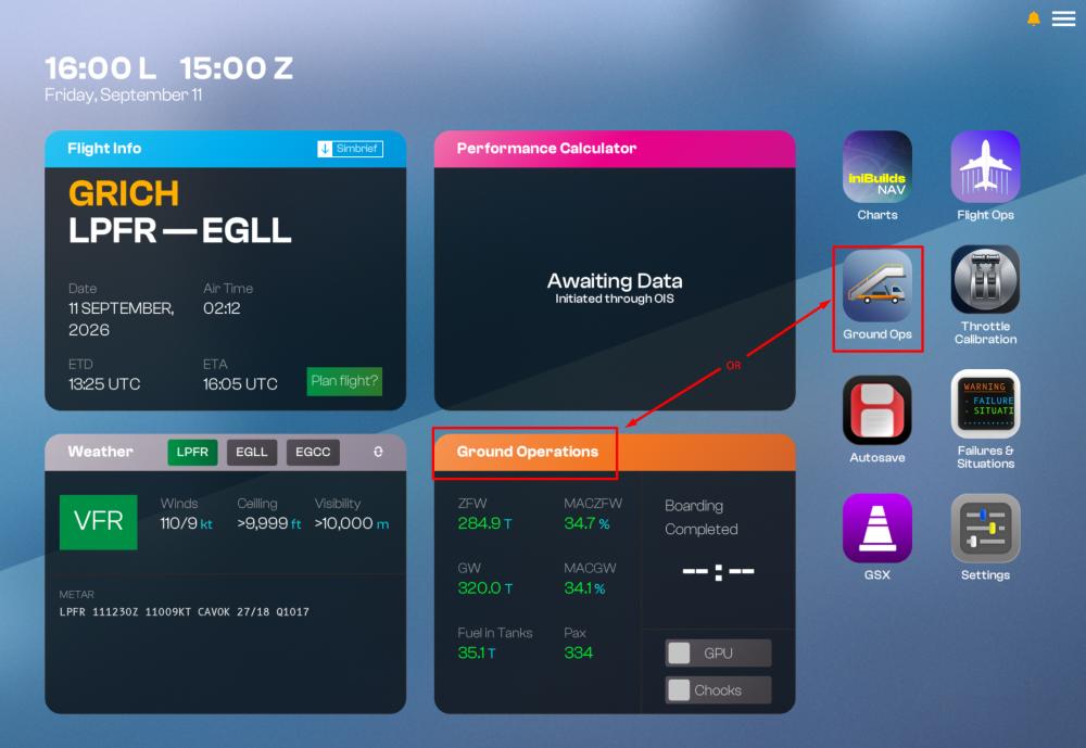
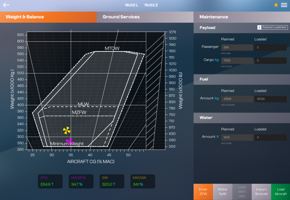
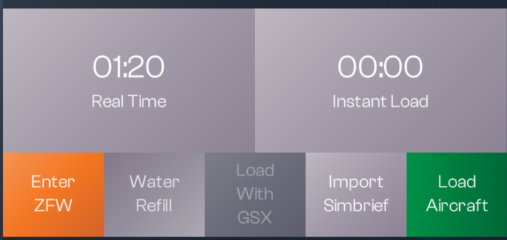
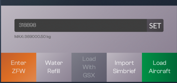
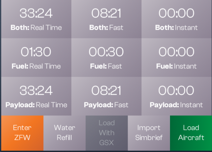
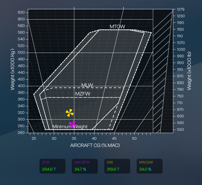
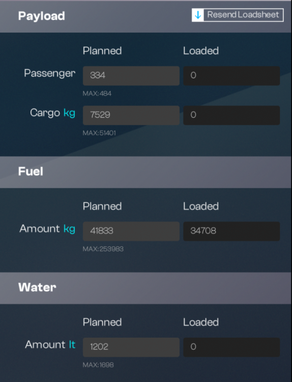
Fuel, Payload & Water Management (EFB)Before you fly, you must set your Passenger and Cargo Loads (PAYLOAD), Fuel Load (FUEL) and Potable Water load (WATER) via the Electronic Flight Bag (EFB) - Ground Operations app on the Weight & Balance page. You can set these values manually or import them through SimBrief for Progressive (Real Time/Fast) or Instant loading onto the aircraft. Both methods are explained below. For loading with GSX, please refer to the 'How to - GSX Integration - Setup & Operation' page instead. (Click to enlarge image) (Click to enlarge image) Overview - Side PanelDedicated buttons and text fields on the side panel function as follows: RESEND LOADSHEET: Resends the final loadsheet to the OIT AOC and FMS ATC pages. PASSENGER: Set your Planned passenger quantity (Max 484) and see currently Loaded quantity. CARGO: Set your Planned Cargo weight (Max 51,401 KG) and see currently Loaded weight. FUEL: Set your Planned Fuel weight (Max 253,983 KG) and see currently Loaded weight. WATER: Set your Planned Potable Water weight (Max 1,698 KG) and see currently Loaded weight. (Click to enlarge image) ENTER ZFW: Set your Planned payload as a Zero Fuel Weight (Max 369,000 KG) directly. This will automatically assign a Passenger and Cargo load to reach Planned ZFW. (Click to enlarge image) WATER REFILL: Load your Planned Potable Water weight in Real Time or Instantly via the pop-up. (Click to enlarge image) IMPORT SIMBRIEF: Autofills all the Planned fields on the Payload, Fuel and Water sections with appropriate values from your Simbrief OFP. Note: Requires SB User ID to be set on the Settings - 3rd Party Settings Page first. LOAD WITH GSX: Loads the Simbrief Payload, Fuel and Water quantity through GSX if Integration is enabled. Note: For loading with GSX, please refer to the 'How to - GSX Integration - Setup & Operation' page instead. (Click to enlarge image) LOAD AIRCRAFT: Load your Planned Payload and Fuel quantities independently (or together) into the aircraft in Progressively (Real Time/Fast) or Instantly via the pop-up. Real Time (MM:SS) = Loads at SME validated average loading rates for Passengers, Cargo and Fuel. The time shown is calculated based upon the difference in Planned vs Loaded values. Fast (MM:SS) = Loads approximately 3x faster than the calculated Real-Time rate. Instant = Loads as soon as the button is pressed. (Click to enlarge image) Overview - Weight & Balance ChartZFW: Zero Fuel Weight - Current (LIVE) in the chosen weight measurement units (LBS/KG). MACZFW: Current Center of Gravity (CG) positions shown as a % of MAC that refers to the CG at curent Zero Fuel Weight. GW: Gross Weight - Current (LIVE) in the chosen weight measurement units (LBS/KG). MACGW: Current Center of Gravity (CG) positions shown as a % of MAC that refers to the CG at current Gross Weight. W&B Diagram: Visual plot of the Aircraft CG (x axis) and Weight (y axis), to assess whether they fall within the shown Max ZFW (MZFW), Max Landing Weight (MLW) and Max Takeoff Weight (MTOW) limits. The ZFW / MAC ZFW is shown in magenta. The GW / MACGW is shown in yellow. (Click to enlarge image) Note: You can change between KG or LBS via the EFB Simulation Settings page. For more information, refer to the How to - Change Weight Units (KG/LBS) guide. Progressive Loading (Real-time / Fast)Press IMPORT SIMBRIEF or manually enter the Planned Passenger, Cargo, Fuel and Water Quantities. ⚠️ Enter your planned ZFW and ZFWCG into the FMS FUEL & LOAD Page. ⚠️ Press LOAD AIRCRAFT and select PAYLOAD / FUEL / BOTH: REAL TIME (MM:SS) on the left most side, OR PAYLOAD / FUEL / BOTH: FAST (MM:SS) in the middle Press WATER REFILL and select REAL TIME The Loaded quantities will start updating and the timer will run in the background. Note: The buttons will grey out when active or not available. Instant LoadingPress IMPORT SIMBRIEF or manually enter the Planned Passenger, Cargo, Fuel and Water Quantities. ⚠️ Enter your planned ZFW and ZFWCG into the FMS FUEL & LOAD Page. ⚠️ Press LOAD AIRCRAFT and select PAYLOAD / FUEL / BOTH: INSTANT on the right most side Press WATER REFILL and select INSTANT The Loaded quantities will update instantly. Note: The buttons will grey out when active or not available. ⚠️Note: Always enter your ZFW and ZFWCG before fuelling to ensure correct CG loading. ⚠️ A GWCG above 40.5% may cause the aircraft to tip backwards. Entering your ZFW and ZFWCG on the FMS ensures the Fuel Quantity Management System (FQMS) can perform active CG targeting during the fuelling process to maintain GWCG within those limits. Failure to do so means the FQMS will fall back to a "single vector method," filling the tanks using a hardcoded, safe default sequence rather than an optimized distribution. This safe default is passive, meaning it prevents exceedance but does not prevent you from reaching the limit. Whenever this limit is reached, fuelling will be stopped automatically to prevent tipping. Note: Changing ZFW or FUEL while airborne may affect VNAV and fuel calculations. You should only change these values while on the ground or whenever it is safe to do so.

-
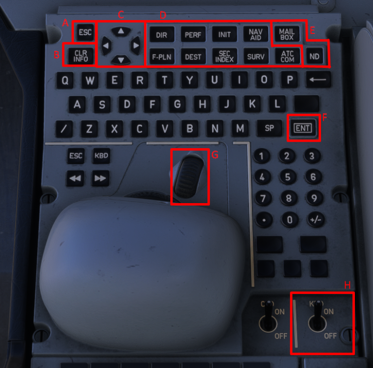
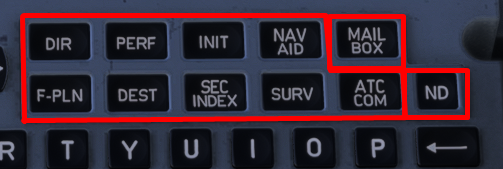
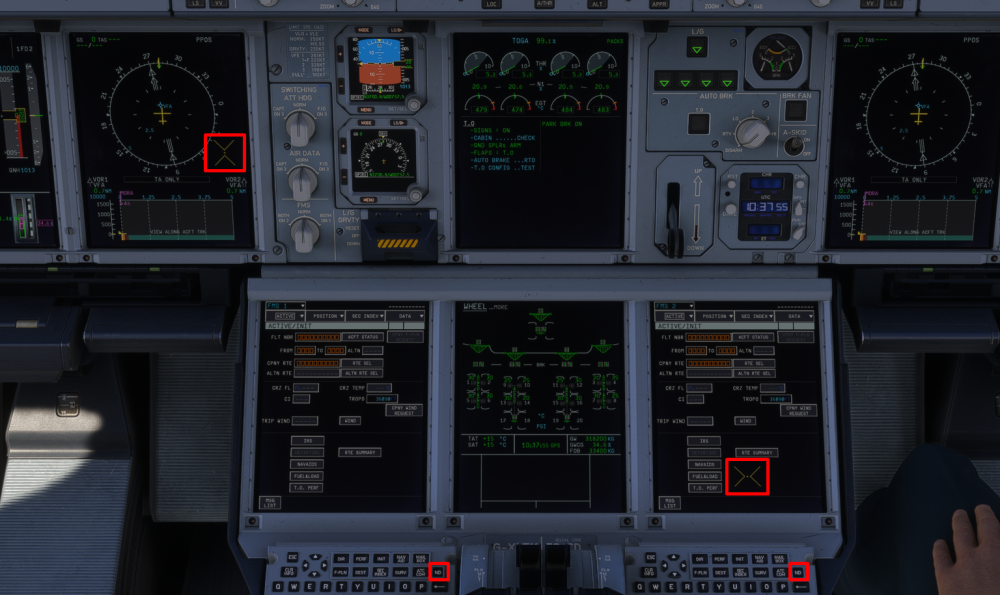
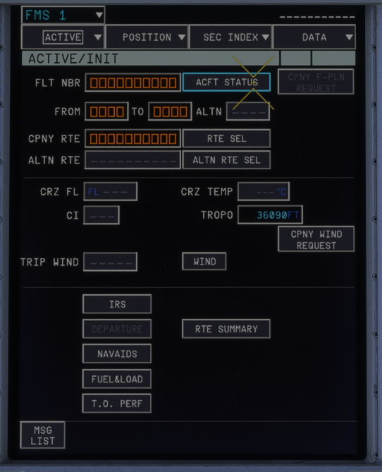
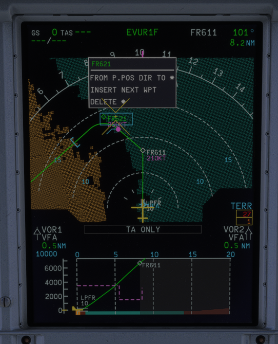
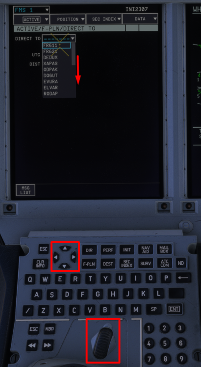
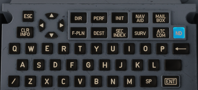
The Keyboard and Cursor Control Unit (KCCU) is part of the Control and Display System. They are directly connected to all the display units for normal operations and for reconfiguration purposes. There are two identical Keyboard and Cursor Control Units (KCCUs) on the pedestal: ‐ One KCCU for the Captain (CAPT) side FMS/ND ‐ One KCCU for the First Officer (F/O) side FMS/ND You can use the KCCUs to: ‐ Display the various FMS pages on the MFD ‐ Enter and modify data on the MFD FMS pages ‐ Perform some flight plan revisions on the ND. - Interact with the MAILBOX (Click to enlarge image) The important KCCU controls for the MFD are: (A) The ESC key Cancels the current field edition, or The field returns to the last valid value. Closes a pop-up window or a menu. (B) The CLR INFO key Clears the message that is currently displayed in the FMS, ATC COM, or SURV message area. (C) The Direction UP/DOWN ARROW keys. Work similarly to the KCCU scroll wheel to scroll through a page or changes the selection in an option-list. Example, on F-PLN page, move between waypoints line-by-line. Also used for stepping between waypoints when on ND PLAN mode for flight plan preview. Example, on DEPARTURE or ARRIVAL pages, required for scrolling between dropdown options-list to select the Runways, SID/STAR/APPR etc. (D) The FMS shortcut keys Used as an alternative way to switch between the various MFD pages. Moves the cursor back to the MFD, if the cursor was previously on another display such as ND or MAILBOX. DIR: Displays the FMS DIRECT TO page on the MFD PERF: Displays the FMS ACTIVE/PERF page (on the panel that corresponds to the active flight phase) on the MFD INIT: Displays the FMS ACTIVE/INIT page on the MFD NAV AID: Displays the FMS POSITION/NAVAIDS page on the MFD F-PLN: Displays the top of the flight plan on the FMS ACTIVE/F-PLN page on the MFD DEST: Displays the bottom of the destination flight plan on the FMS ACTIVE/F-PLN page on the MFD SEC INDEX: Displays the FMS SEC INDEX page on the MFD SURV: Displays the SURV CONTROLS page on the MFD ATC COM: Displays the ATC COM REQUEST page on the MFD (E) The ND, MFD and MAILBOX keys ND: When pressed, moves the cursor to the onside ND MAILBOX: When pressed, moves the cursor to the mailbox (F) The ENT key - Edits an entry field: The cursor is positioned in the field, and is ready for a new entry When data is entered, another click validates the entry, and the cursor moves to the field or button that is most likely to be used next - Edits an option-list: The option-list opens, and the first option is selected You may use the scroll wheel or the direction arrow keys, to change the selected option, if required Another click validates the selection, and the cursor moves to the field or button that is most likely to be used next - Activates the highlighted button. (G) The Scroll Wheel Works similarly to the Direction UP/DOWN arrow keys. Changes the selection in an option-list Scrolls through a page (e.g. F-PLN page or message list (H) The KBD Power Switch Master ON/OFF toggle for functions of the keyboard letters and numpad. Switch is normally left ON CURSOR OPERATION - MOVING BETWEEN DISPLAYSEach KCCU displays a different cursor. In the real aircraft they would be individually controlled by their respective Cursor Control Device (CCD) trackball, however for simulation purposes they will simply follow your mouse cursor within the respective boundaries of the currently active CAPT/FO display. Captain (Left) and First Officer (Right) Cursors The cursor is moved between the MFD, ND and MAILBOX displays by one of the following methods: via KCCU: Click the ND, Mailbox or any MFD Page keys to move the cursor to that display respectively. via Mouse: Click once anywhere on the display to make it the active cursor display (Click to enlarge image) INTERACTIVE ELEMENTSWhen the cursor is moved over an interactive element of the display unit, a light blue box appears around this element. You may then left-click on your mouse to begin the interaction such as allow text input or open the relevant page/drop-down menu for that element. For example on the MFD FMS Page, the 'ACFT STATUS' button below is highlighted to indicate you can click it to open the 'ACFT STATUS page'. (Click to enlarge image) For example on the ND, the waypoint 'FR621' is highlighted to indicate it can be clicked top open the drop-down menu of various FMS functions for that waypoint. (Click to enlarge image) DATA INPUT - KCCU OR KEYBOARDWhen you click on a data field, you will see a light blue flashing cursor box within the data field meaning you can use the alpha-numeric keys on the KCCU to enter the desired values. Click the ENT key on the KCCU to confirm the input or the ESC key to exit the field. To activate KEYBOARD INPUT, press the Left Ctrl key on your keyboard once. You will see an amber KEYBOARD INPUT ACTIVE message at the bottom to confirm activation. Then you can use your hardware keyboard for data input. Press Enter on your keyboard to confirm the input. The KEYBOARD INPUT mode will de-activate automatically after. To manually de-activate KEYBOARD INPUT, you can press Left Ctrl key again once. Then click the ESC key on the KCCU to exit the field. LIST OPTIONS SELECTION - ARROW KEYS OR SCROLL WHEELWhen an option-list opens, the first option is selected. You may choose the other options on the list by one of 2 methods below: Cursor Selection: Hover your cursor over the desired option and left click to confirm selection. KCCU Selection: Use the UP/DOWN arrow keys or the SCROLL WHEEL to navigate between all of the options on the list. Then click the ENT key to confirm the selection. (Click to enlarge image)




-
Attached below is the Aircraft Manual for the iniBuilds A380 Airliner for your reference. iniBuilds A380 Manual 1.2.pdf
-
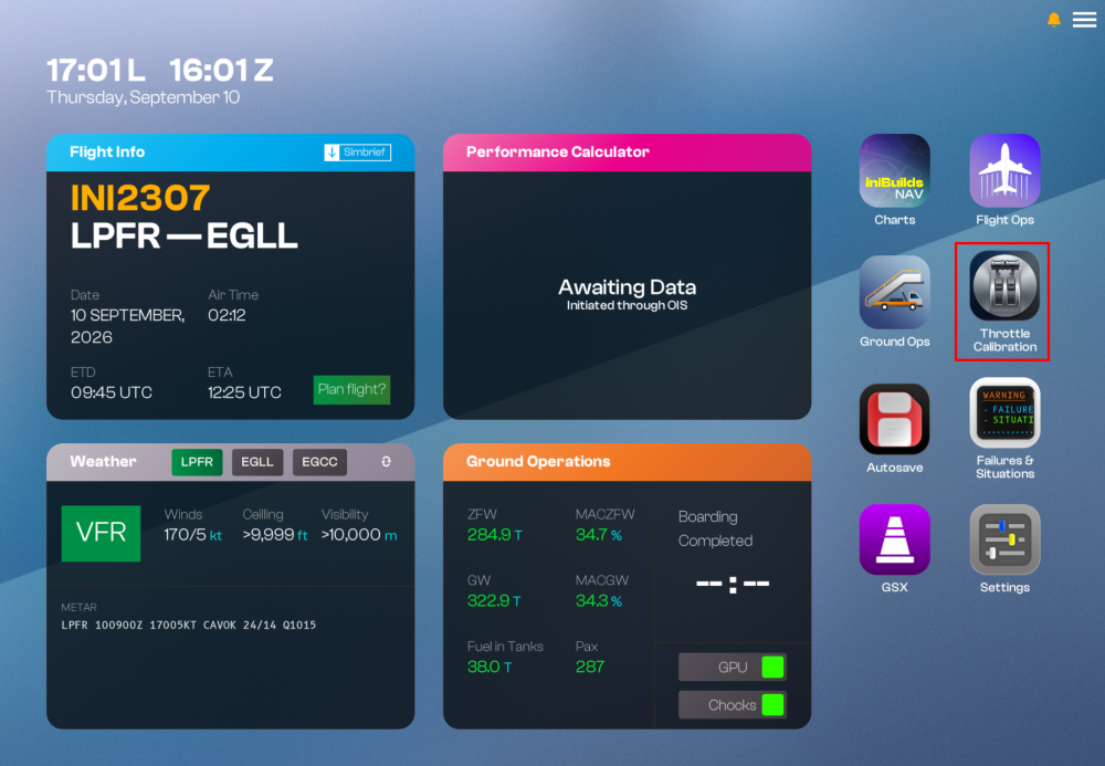
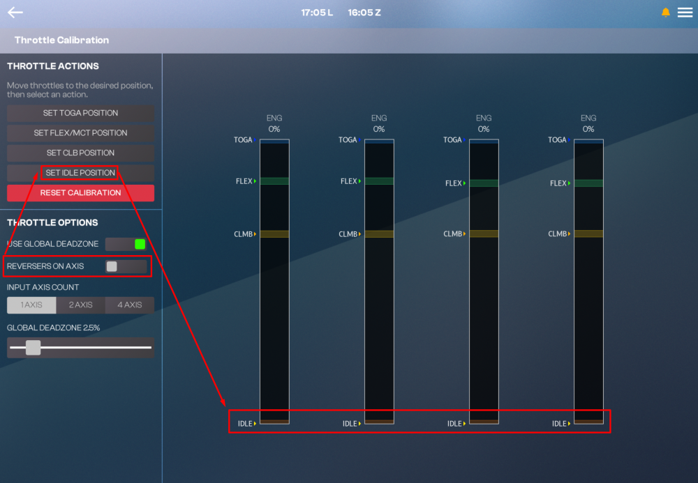
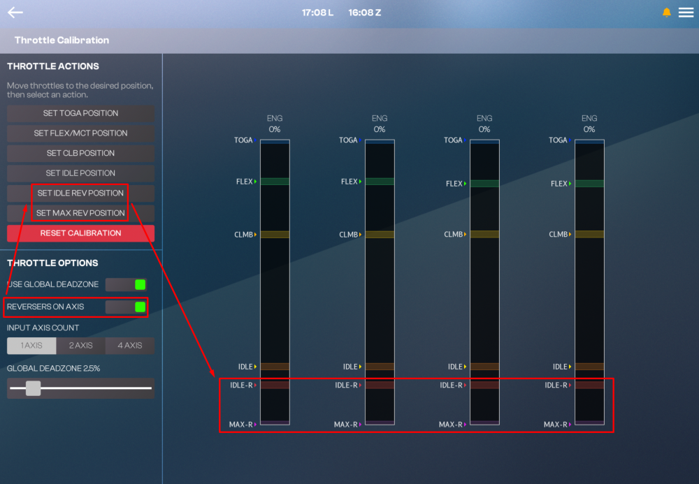
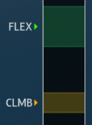
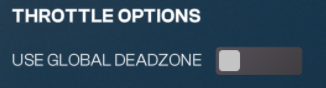
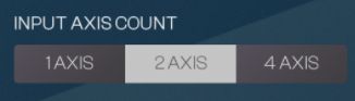
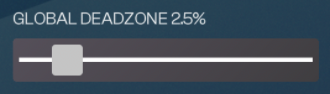
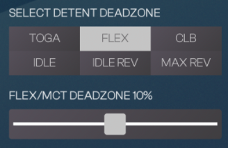
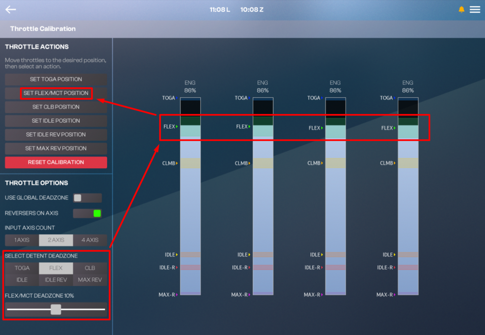
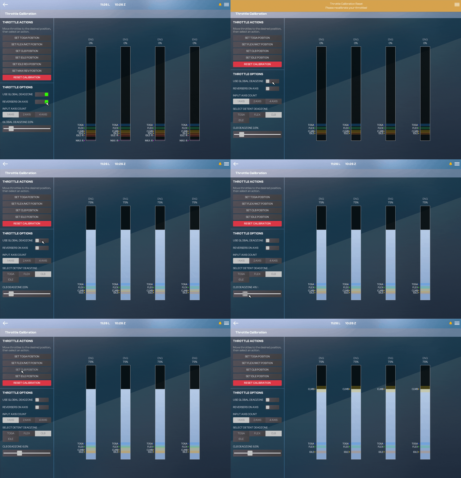
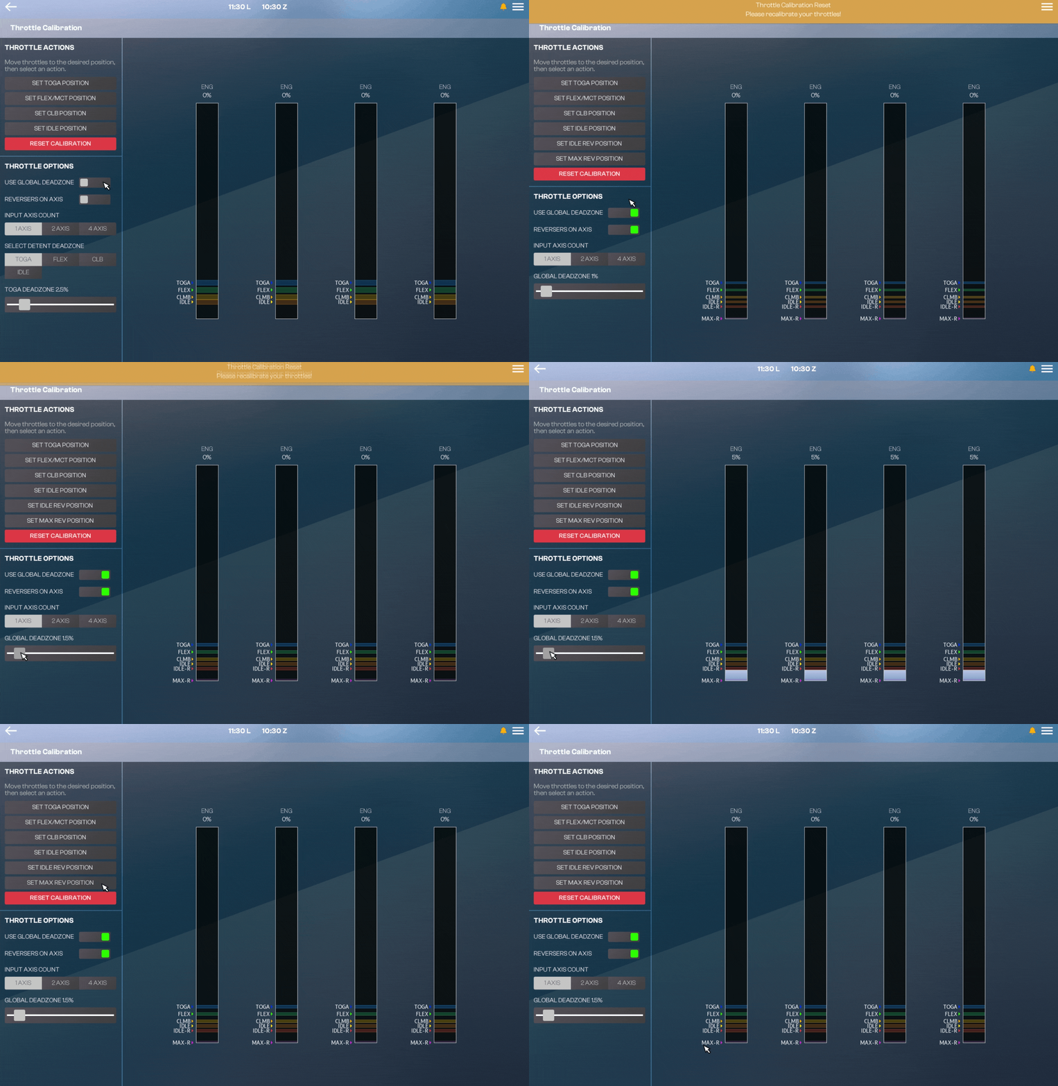
Throttle Calibration Page (EFB)Before you fly, you must calibrate your throttles via the Electronic Flight Bag (EFB) - Throttle Calibration page. (Click to enlarge image) Throttle Calibration ProcessTypically the throttle calibration is done in the following order Ensure that Throttle Axis or Throttle Axis 1 to 4 are assigned in the MSFS Control settings. Set desired REVERSERS ON AXIS option Set desired INPUT AXIS COUNT option Set desired INPUT DEADZONE % Move your hardware throttle axis to the position you want to define as a detent (e.g. IDLE/CLB/FLX/TOGA) Click the SET (DETENT) POSITION button on the EFB to define the current position to the detent chosen Observe new detent position shown on the diagram on the right. Repeat Steps 4 to 7 for each desired detent. Reversers on Axis OptionVerify whether your hardware has a reverse thrust on an axis or not then choose the appropriate option. 'REVERSERS ON AXIS' is set to OFF: The bottom most position of your hardware axis (0%) will be assignable to the IDLE detent position. You may have to bind 'HOLD' / 'TOGGLE REVERSE THRUST' sim control binding to an additional button / input on your hardware to use reverse thrust. This option is recommended for majority of consumer flight simulation hardware (including Xbox Controllers). 'REVERSERS ON AXIS' is set to ON: The bottom most position of your hardware axis (0%) will be assignable to the MAX REV detent position for thrust reverser operation. You can additionally define separate IDLE and IDLE REV detent positions. This option is recommended for hardware such as the WinCtrl or TCA Airbus Throttle Quadrants. (Click to enlarge image) Note: The A380 only has reversers on the inboard engines (ENG 2 and 3). This is to reduce risk of Foreign Object Debris (FOD) ingestion as the outboard engines (ENG 1 and 4) are positioned much further out on the wing, closer to the runway edge Input Axis Count OptionVerify whether your hardware has 1, 2 or 4 independent hardware axis available for throttle control, then choose the appropriate option. This changes how the calibration values are copied across ENG1 to ENG4. Input Deadzone OptionYou can configure the Input Deadzone % either: Globally: Apply the same deadzone to all detents, or Independently: Set a unique deadzone for each detent. This is controlled via the USE GLOBAL DEADZONE toggle. The current deadzone boundaries are displayed on the axis diagram (right side) as colored boxes above and below your current AXIS % value. What it means: The detent activates whenever the ENG1 to ENG4 % values fall within the defined box. Larger deadzone % = larger colored box = Detent engages across a wider range of hardware movement. Smaller deadzone % = smaller colored box = Detent requires more precise positioning 'USE GLOBAL DEADAONE' is set to ON: Applies the same deadzone to all detents. Adjust by moving the GLOBAL DEADZONE % slider. You will see the boundary boxes change visually for all detents. 'USE GLOBAL DEADAONE' is set to OFF: Sets a unique deadzone to each detent. Adjust by choosing a detent under SELECT DETENT DEADZONE and then moving the XXXX DEADZONE % slider (where XXXX is your chosen detent). You will see the boundary boxes change visually for the chosen detent. Applying a Deadzone %Use the slider to choose the desired 'DEADZONE %' value (Default is 2.5%). Move your hardware throttle axis to where you want to define a chosen detent. Click the SET (DETENT) POSITION button to apply the set value to your detent. Example - Applying a 10% Deadzone to FLEX/MCT detent (Click to enlarge image) Example Throttle Calibration ProcessExample #1 - Defining a CLB detent with Reverser On Axis = NO and independent Deadzone % Set REVERSERS ON AXIS to OFF Move your hardware axis physically to where you want to define the CLB detent. Set USE GLOBAL DEADZONE toggle to OFF Select the CLB detent from SELECT DETENT DEADZONE Set your desired 'CLB DEADZONE %' using the slider. Press the 'SET CLB POSITION' button on the EFB. Verify on the diagram on the right a CLIMB > appears showing the newly defined CLB detent position, with the relevant % above. (Click to enlarge image) Example #2 - Defining a Max Reverser detent with Reverser On Axis = YES and Global Deadzone % Set REVERSERS ON AXIS to ON Move your hardware axis physically to where you want to define the MAX REV detent. Set USE GLOBAL DEADZONE toggle to ON Set your desired 'GLOBAL DEADZONE %' using the slider. Press the 'SET MAX REV POSITION' button on the EFB. Verify on the diagram on the right a MAX-R > appears showing the newly defined MAX REV detent position, with the relevant % above. (Click to enlarge image)


-
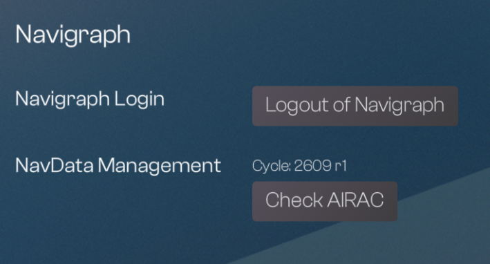
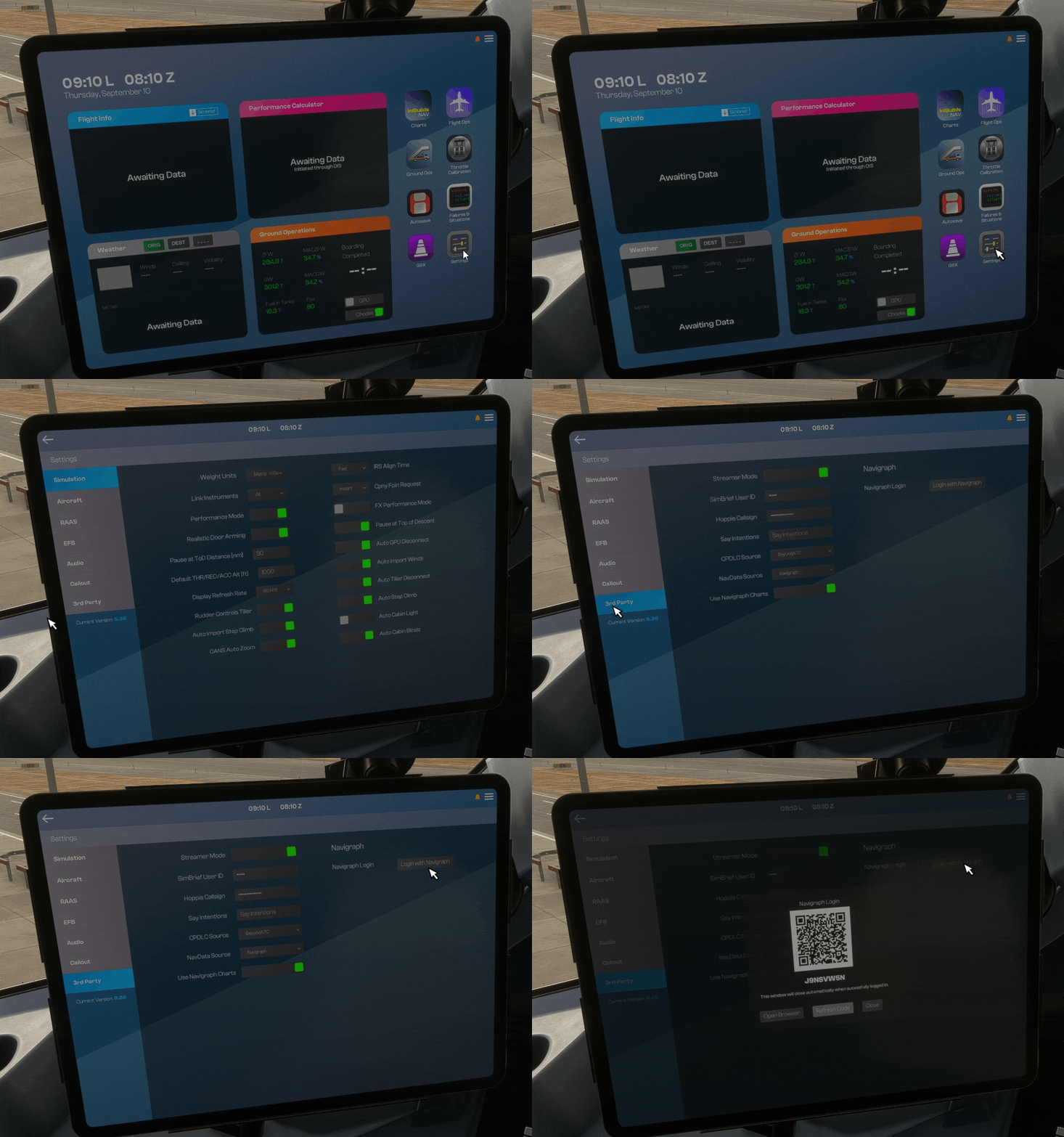
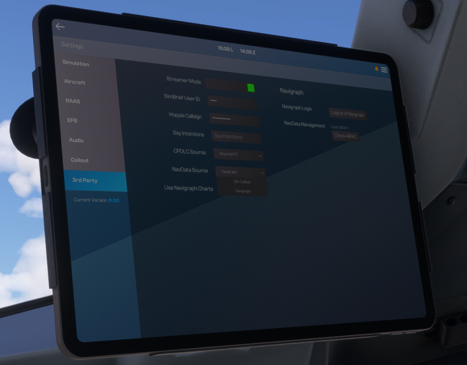
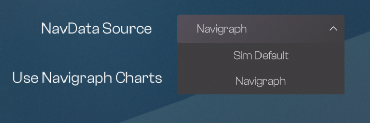
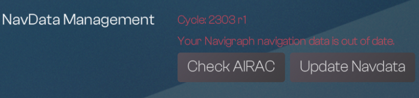
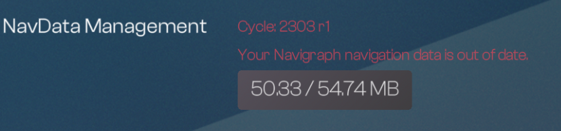
Before your first flight, you must set your preferred navigation database (Navdata) via the Electronic Flight Bag (EFB) third-party settings page. (Click to enlarge image) Navdata OptionsOption Source Updates Notes Sim Default Microsoft (built-in) Automatic May conflict with scenery/3rd-party packages to cause - Missing or incomplete SIDs / STARs / Approaches - Outdated or misaligned runway data Navigraph External (subscription) Manual (via EFB 3rd Party Settings Page) Independent Changing Navdata SourceYou can swap between 'SIM DEFAULT' and 'NAVIGRAPH' navdata by simply clicking on its respective option from the dropdown. This can ONLY be done on the ground without the engines running. Note: Changing navdata source will completely wipe the FMS data. You should only do this prior to completing your FMS preparation as a result. Note: You should restart your flight after changing navdata sources or updating navdata Navdata is loaded into memory when you spawn into a scenario. Exiting to main menu and reloading into the scenario after changing sources (or updating navdata) avoids multiple/outdated databases flooding memory and causing session instability. Navigraph NavdataThere is a default cycle included (2303 R1). Users with an active Navigraph subscription can update to the latest navdata version by linking their account through the EFB. CONNECT TO NAVIGRAPHI (Click to enlarge image) Complete the authentication process by Scanning the shown QR Code, OR Pressing the OPEN BROWSER button to open your default web browser After you have completed the authentication steps the EFB will update to show the additional 'LOGOUT OF NAVIGRAPH' and 'CHECK AIRAC' options. (Click to enlarge image) UPDATE NAVDATAPress CHECK AIRAC button to fetch the latest navdata cycle and revision. You will see an 'Your Navigraph navigation data is out of date' error if the installed cycle is older than the latest available online. (Click to enlarge image) Click the 'UPDATE NAVDATA' button. The button will change into a progress bar once download commences. Once completed, you will see a 'Navigraph Navdata Updated' notification at the top of the screen and the cycle number will update to the latest. (Click to enlarge image) Note: This should ONLY be done on the ground without the engines running. This process requires an active internet connection and may take a few minutes whilst the data is downloaded from the servers. This will also completely wipe the FMS data. RESET NAVIGRAPHAfter an A380 Airliner product update it is recommended to reset your credentials and refresh your Navigraph token to avoid issues with Charts, Enroute Map or FMS Navdata functions. It is also sometimes necessary as a troubleshooting step. Simply click the 'LOGOUT OF NAVIGRAPH' button to restart the process. (Click to enlarge image) Note: It is recommended to switch navdata to SIM DEFAULT if you have logged out. You should conduct the UPDATE NAVDATA process again after re-connecting your Navigraph account.

-
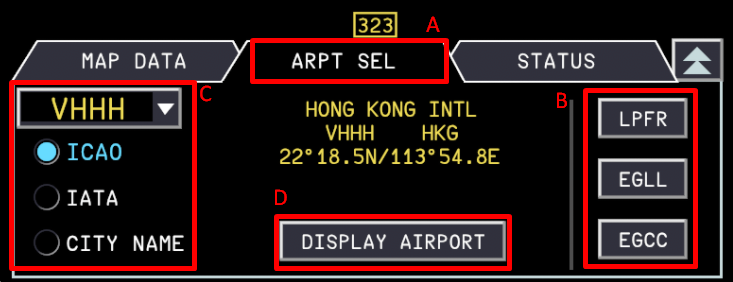
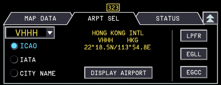
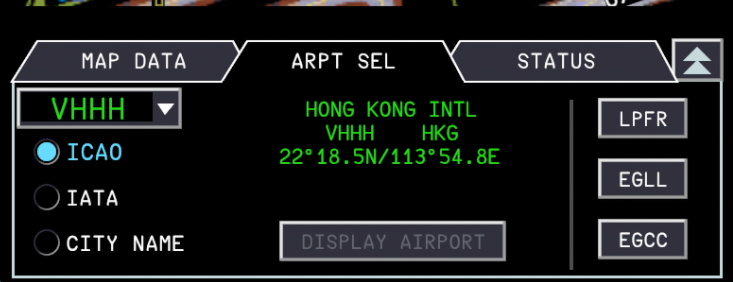
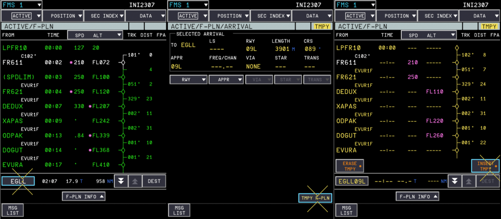
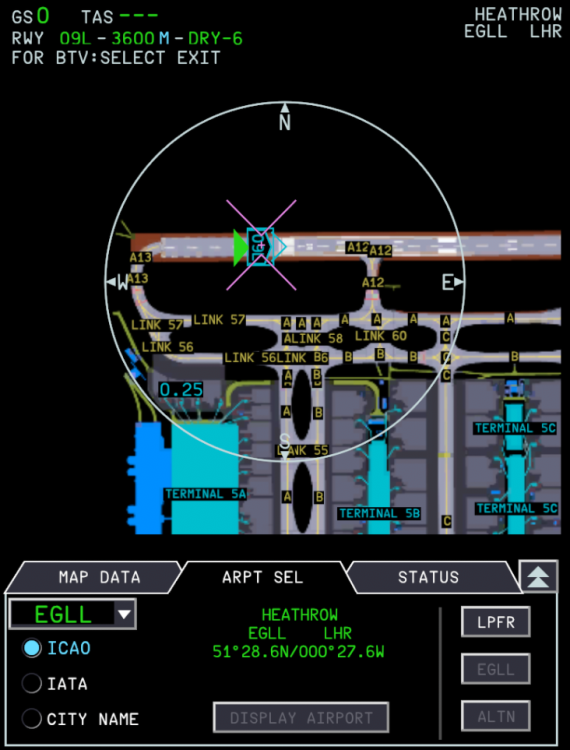
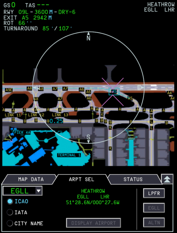
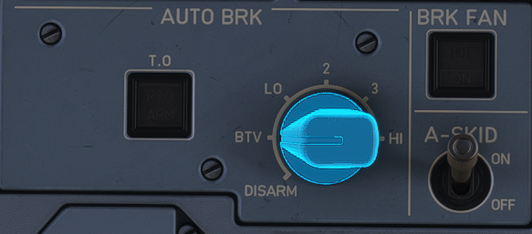
The Brake To Vacate (BTV) function optimizes the autobrake deceleration on landing in order to reach the selected runway exit point/ manually entered landing distance. The system takes into account the selected runway condition/braking action in its calculations. Once armed, the system works autonomously to delay braking in order to reduce brake wear, optimize the runway occupancy time (ROT) and improve passenger comfort. SETTING UP BTVIn order for BTV to function, it needs information such as your target stopping distance. This information can be provided by Runway and Runway Exit Selection on the On-board Airport Navigation System (OANS) on the ND. Note: This feature requires an active Navigraph Unlimited subscription. A valid airport map must be loaded on the OANS, which can only be done after successfully connecting your Navigraph account on the EFB 3rd Party Settings page. For more information, see the below CONNECT TO NAVIGRAPH section of the OANS FAQ post. Step 1: Choose Landing Runway on FMSPress the F-PLN shortcut key to go to the FMS F-PLN page At the bottom left corner, select your DEST airport and select the Landing RWY - you can also select your APPR and STAR on this page, however the BTV system only requires the runway at minimum to function Choose TMPY F-PLN and then INSERT TMPY to confirm the selection. (Click to enlarge image) Step 2: Set OANS to your DEST airport Whilst on the OANS display, the currently displayed airport moving map (AMM) can be changed via the ARPT SEL function page as follows: Change to PLAN mode via the ND Mode Selector Knob Change the range to ZOOM via the ND Range Selector knob Move the KCCU cursor to the ND screen by - Clicking anywhere on the ND screen, OR - Clicking the ND key on the KCCU Click the Additional Function Button at the bottom-right corner of the ND Select the (A) ARPT SEL tab Choose from the (B) FMS AIRPORTS list to display your Destination Click the (D) DISPLAY AIRPORT button to make it the active displayed airport. (Click to enlarge image) Note: You can only view other airports in the ND PLAN mode. The airport navigation display is locked to the aircraft position in NAV or ARC modes, so you must switch to PLAN mode in order to center the map on the selected airport. Note: Your selected airport ICAO/IATA/Info will appear in different colors based upon display status. Yellow when it is the not active airport displayed on the ND Green when it is the active airport displayed on the ND Step 3: Choose Landing Runway and Runway Exit on the OANSClick-and-drag to center the map on your desired runway. Click on the Runway Identifier with a green triangle next to the threshold. You will see a FOR BTV: SELECT EXIT message appear on the top left corner as confirmation. Then select the desired Runway Exit by moving your cursor to the taxiway identifier and clicking it. You can also unselect it the same way by clicking on it again Once a target Exit is chosen, A blue line will appear along the landing runway to the selected exit showing the chosen BTV target exit, AND On the top left corner of the ND, you will see the chosen RWY (and its LDA), EXIT as well as the corresponding Runway Occupancy Time (ROT)(in seconds) and TURNAROUND time (in minutes) for MAX REV or REV IDLE usage respectively. (Click to enlarge image) Note: You must choose an exit beyond the DRY or WET ROW Stop Bar If you chose an exit that is before the DRY or WET ROW line, the BTV will not be able to stop to reach the exit in time. BTV ARMING & ENGAGEMENTThe BTV autobrake mode arms when the following conditions are met: A BTV Runway and Exit is selected, AND A/BRK ROTARY SELECTOR is set to BTV (Click to enlarge image) Once successfully armed, The PFD FMA will show BTV in blue (Click to enlarge image) The BTV autobrake mode engages on landing if any one of the conditions is met: immediately after ground spoilers extension if the NLG is on ground; OR 5s after ground spoilers extension if NLG is not on ground (Click to enlarge image) BTV DISARMING & DISENGAGEMENTThe autobrake disarms if any one of the conditions is met: The A/BRK ROTARY SELECTOR is reset to DISARM, OR The selected landing runway on the OANS is modified, OR The BTV exit is deselected, OR The FMS runway is changed to a runway that is different from the selected landing runway, OR A go-around is performed below 600 ft. The reversion occurs during the go-around, when the aircraft climbs above 600 ft. The computation is based on the minimum between the radio altitude, and the aircraft height above the runway threshold. The autobrake disengages if any one of the conditions is met: The aircraft ground speed reaches the BTV disconnection speed (approx. 10 kt), OR The flight crew uses the brake pedals, OR The flight crew presses the A/THR instinctive disconnect pushbutton, OR The ground spoilers retract or disarm. When autobrake disengages the the following happens: An AUTO BRK OFF aural alert sounds The MASTER CAUT lights comes on The AUTO BRK OFF memo appears on the PFD and WD.


-
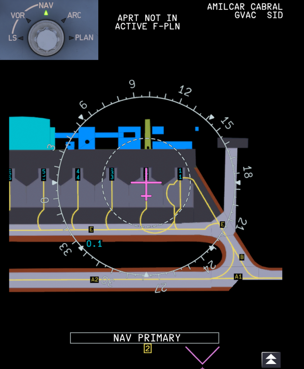
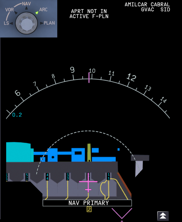
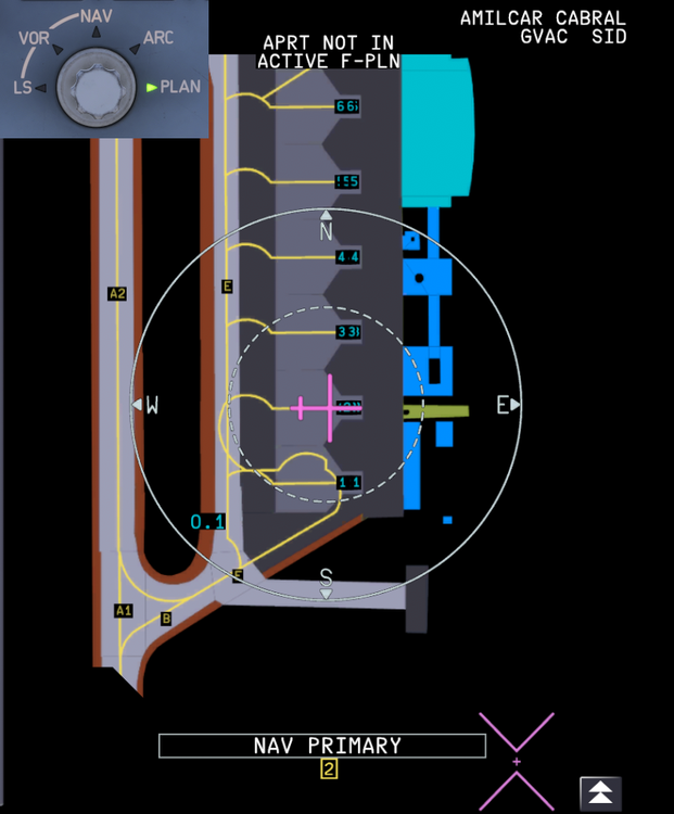
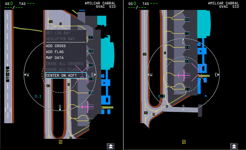
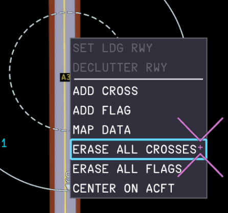
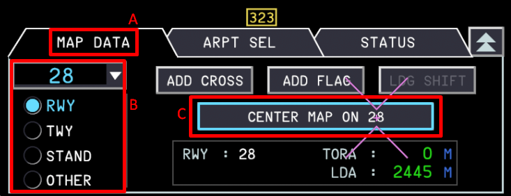
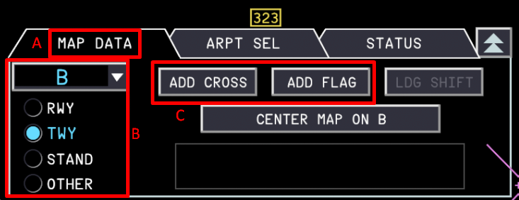
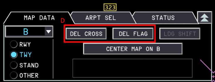
The On-board Airport Navigation System (OANS) on the iniBuilds A380 Airliner provides an Airport Moving Map (AMM) directly on your Navigation Display (ND) and Multi-Function Display (MFD). It enhances situational awareness by displaying your real-time position, airport layout, runway hold points, and custom markers. The AMM is accessed by setting the ND Range Selector Knob to 'ZOOM' on the EFIS Control Panel while in ROSE NAV, ARC or PLAN modes. The Keyboard and Cursor Control Unit (KCCU) is used to interact with the airport navigation display. (Click to enlarge image) CONNECT TO NAVIGRAPHConnect your Navigraph account via the Electronic Flight Bag (EFB) third-party settings page. I (Click to enlarge image) Complete the authentication process by Scanning the shown QR Code, OR Pressing the OPEN BROWSER button to open your default web browser After you have completed the authentication steps the EFB will update to show the additional 'LOGOUT OF NAVIGRAPH' and 'CHECK AIRAC' options. (Click to enlarge image) OANS - CONTROLS AND INDICATORSWhen the ND Range Selector knob is set into the ZOOM position, the AMM is displayed on the ND the knob can be turned clockwise or counter-clockwise to increase/decrease the range of the AMM the knob has a range of five different ZOOM levels (5, 2, 1, 0.5 and 0.25 NM) the green knob indicator light remains in ZOOM position at the above five ZOOM levels. Note: Your sim may freeze for a few seconds ONCE per airport map that is loaded in to memory for the first time each flight session. When the ND Range Selector knob is moved out of the ZOOM position, the AMM is no longer displayed on the ND the ND returns to normal flight navigation display mode. The KCCU cursor and keyboard are be used to, Activate interactive functions of the ND Move the AMM by click-and-drag action Enter data on the OANS function pages. The KCCU Cursor can be moved to the ND by, Clicking anywhere on the ND screen Clicking the ND key on the KCCU The ND Mode Selector Knob allows you to display the airport navigation display differently in the following modes, ROSE-NAV ARC-NAV PLAN (Click to enlarge image) ARPT SEL FUNCTION- CHANGING DISPLAYED AIRPORT MAPWhilst on the AMM display, the currently displayed airport map can be changed via the ARPT SEL function page as follows: Change to PLAN mode via the ND Mode Selector Knob Change the range to ZOOM via the ND Range Selector knob Click the Additional Function Button at the bottom-right corner of the ND Select the (A) ARPT SEL tab Choose from the - (B) FMS AIRPORTS list to display your Origin, Destination or Alternate airport; OR - (C) AIRPORT ITEM SEARCH FILTER list by typing in via the KCCU either the ICAO/IATA code of desired airport Click the (D) DISPLAY AIRPORT button to make it the active displayed airport. (Click to enlarge image) Note: You can only view other airports in the ND PLAN mode. Note: Your selected airport ICAO/IATA/Info will appear in different colors based upon display status. MAP FREELOOK FUNCTION- CENTER ON AIRCRAFT / RUNWAY / TAXIWAYThe AMM can be moved around by a simple left click-and-drag action with your cursor anywhere on the map. Note: In the NAV or ARC ND modes, the map will automatically re-center on the aircraft position as soon as you release the cursor. In the PLAN ND mode, to re-center the view onto your aircraft position, Left click with your cursor anywhere on the airport moving map display Select CENTER ON ACFT from the function list that shows up (Click to enlarge image) In the PLAN ND mode, to re-center the view onto a specific runway or taxiway, Click the Additional Function Button at the bottom-right corner of the ND Select the (A) MAP DATA tab Select an item from the (B) MAP ITEM LIST via - RWY filter to list all the runways in database for the active airport map; OR - TWY filter to list all the taxiways in database for the active airport map Click the (C) CENTER MAP ON XXXX button to center the map on the selected item (where XXXX is the selected item from the Step 3) (Click to enlarge image) MARKING FUNCTION- ADD OR REMOVE CROSSES AND FLAGSIn the NAV/ARC/PLAN ND modes, you can add CROSSES or FLAGS to highlight important checkpoints/hotspots or mark off closed taxiways for enhanced situational awareness. The CAPT and F/O sides share these marks. You can add or remove these marks in two ways: via the MAP DATA page on the Additional Functions Menu; OR via the airport moving map display on your present cursor position MAP DATA Page MethodTo add (or remove) a CROSS or FLAG from a map item via the MAP DATA page, Click the Additional Function Button at the bottom-right corner of the ND Select the (A) MAP DATA tab Select an item from the (B) MAP ITEM LIST via - RWY filter to list all the runways in database for the active airport map; OR - TWY filter to list all the taxiways in database for the active airport map Click the (C) ADD CROSS or ADD FLAG button to mark the selected item from the Step 3 above. OR Click the (D) DEL CROSS or DEL FLAG button to unmark the selected item from the Step 3 above. Airport Moving Map Display MethodTo add a CROSS or FLAG anywhere on the map via the airport moving map display, Left click with your cursor anywhere on the AMM display Select ADD CROSS or ADD FLAG from the function list that shows up To remove a specific CROSS or FLAG on the map via the airport moving map display, Left click with your cursor the CROSS or FLAG you wish to remove It will be highlighted with a blue box indicating the it is the selected map item Select DELETE CROSS or DELETE FLAG from the function list that shows up To remove ALL CROSS or FLAG anywhere on the map via the airport moving map display, Left click with your cursor anywhere on the airport moving map display Select ERASE ALL CROSSES or ERASE ALL FLAGS from the function list that shows up Note: All flag and cross marks are automatically deleted from database: ‐ At the start of each flight, when the flight phase of the FWS change to flight phase 1, OR ‐ If the flight crew changes the ANF database cycle.






-
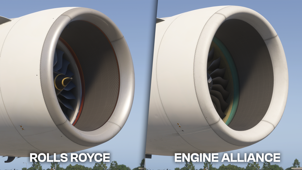
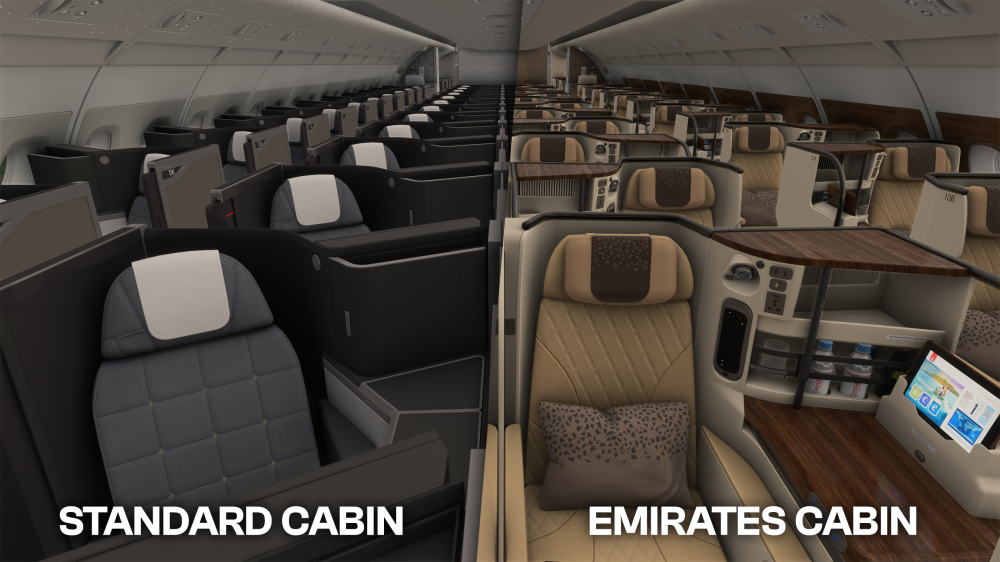
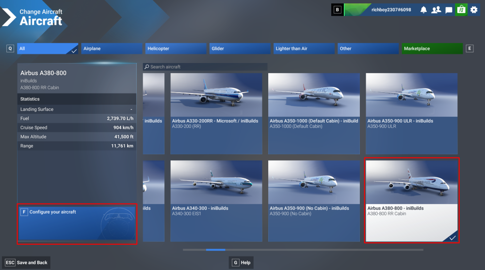
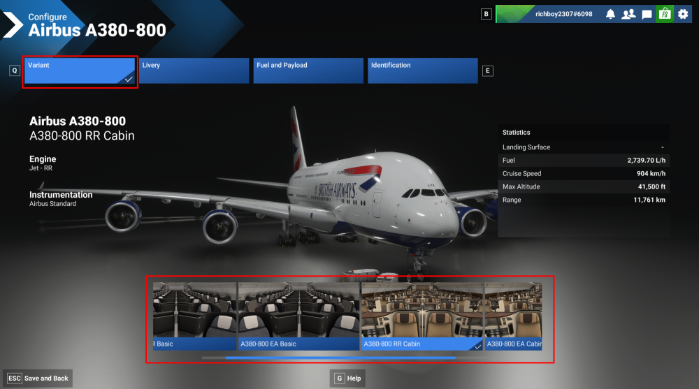
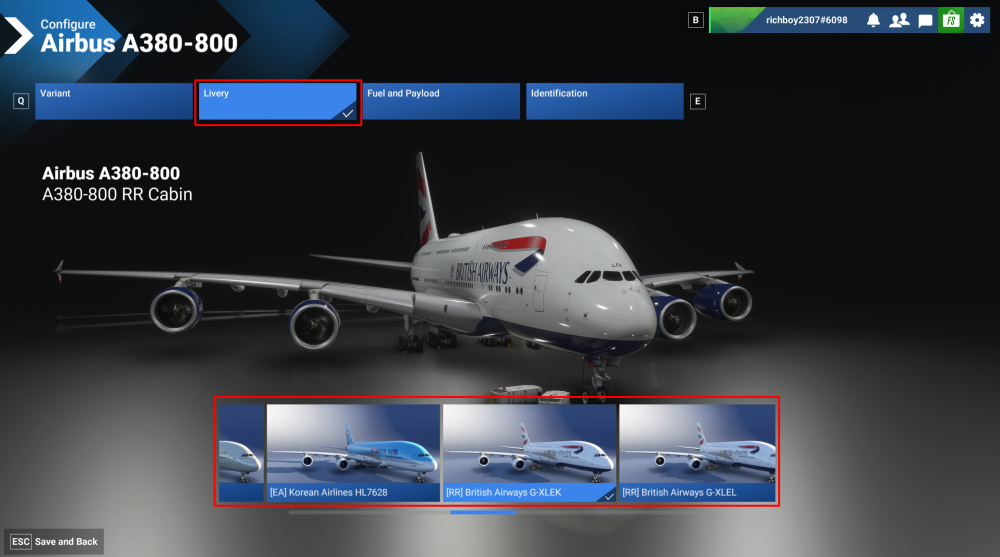
The iniBuilds A380 Airliner for FS2024 comes with both Rolls-Royce Trent 900 and Engine Alliance GP7200 engine variants that each have their own external geometry, sound profile, start and shutdown behaviour, spool dynamics, thrust response and relevant cockpit indications and system behaviour. Additionally, both engine variants can be paired with either a 4-class (Emirates-style) or 3-class (generic) passenger cabin. You can choose your preferred configuration to use with any compatible livery of your choice via the Aircraft Selection Menu. Changing Engine or Cabin Variants Open the Aircraft Selection Menu Find from the list or Search for the 'A380' Choose the 'A380-800' or 'A350-1000' aircraft Select 'Configure your aircraft' at the bottom left corner of your screen via your mouse or by pressing the shown keybind Choose the 'Variant' tab at the top Select 'XX Basic', 'XX Cabin' variant, where XX is the desired engine variant (EA or RR). Basic is the 3-class (generic) type. Cabin is the 4-class (Emirates-style) type. Switch to the 'Livery' tab at the top Choose your desired livery from the list Select 'Save and Back' at the bottom left corner of your screen via your mouse or by pressing the shown keybind Now you can return to the Free Flight menu and select Start Flight to use the selected Engine and Cabin variant of the iniBuilds A380 Airliner.
-
Close the simulator if it is running. Navigate to your your FS24 WASM Folder: Delete all the contents of this folder. This folder and its contents will be re-generated next time you load into a flight with the aircraft.
-
To steer the A220 effectively, first ensure NOSE STEER is turned ON using the button directly under the gear lever. Use your rudder pedals for gentle corrections and straight taxiing, and switch to the tiller-only inputs for sharp turns. When rudder pedals and steering tiller are moved simultaneously, the max deflection is limited to the 9° left / right only. For tiller-only inputs, press the PEDAL DISCONNECT button on the tiller to boost your turning gain for maximum steering angle. The steering tiller commands the nosewheel up to 80° left / right.
-
Use the link below to see an index of all simulator variables (L-Vars and H-Events) and input events that the A220 reads and writes, organized by system. These can be used to read and modify the aircraft state's using external applications. Simulator Variables (L-Vars and H-Events) https://docs.synapticsim.com/pilots/simvars Input Events https://docs.synapticsim.com/pilots/inputs
-
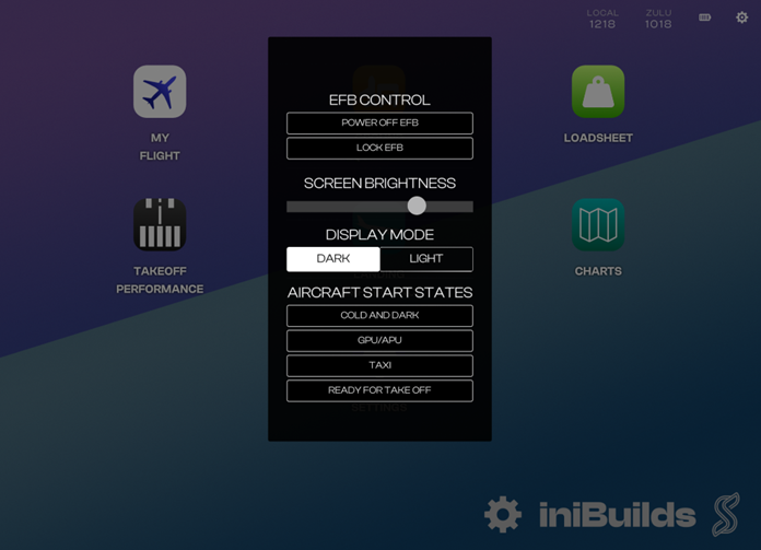
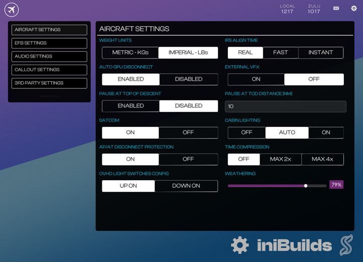
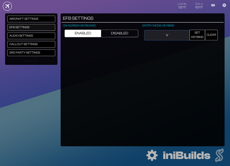
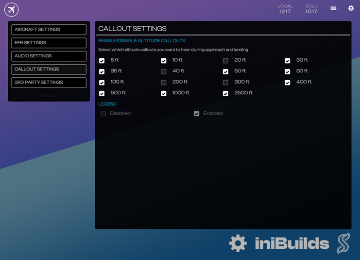
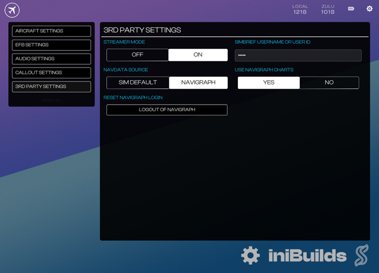
There is an Electronic Flight Bag (EFB) located on both the left and right-side consoles on the A220. EFB Controls MenuPower Off EFB: Click anywhere on the screen to turn back on Lock EFB: Return to Lockscreen Screen Brightness Slider: Adjust brightness of EFB screens Display Mode: Set a DARK or LIGHT theme on the EFB UI Panel States: Select any state to set aircraft systems accordingly Note: Click anywhere on the screen to exit the menu. SettingsSetting menu selector and Version Indicator Settings menu display. Aircraft Settings Weight Units: choose between Metric (KG) and Imperial (LBS) units for Aircraft Systems and EFB. IRS Align Time: choose between Realistic, Fast (60s) and Instant IRS alignment on first power up. Auto GPU Disconnect: automatically disconnects the GPU and Chocks whenever beacon lights are turned on. External VFX: hide any external condensation visual effects for extra performance. Pause at Top of Descent: automatically pauses the sim at the set distance prior to the FMS computed Top of Descent (TOD). SATCOM: toggles the option Satellite Communications equipment on the exterior of the aircraft Cabin Lighting: Allows you to set manual or automatic control of cabin lighting based on time of day. AP/AT Discon Protection: inhibits the automatic disconnection of Autopilot and Autothrust based on excessive turbulence or control inputs. Time Compression: selects the desired simulation rate (upto 4x) OVHD Light Switches Config: chooses whether the switches on the overhead panel should be moved upwards (UP ON) or downwards (DOWN ON) to illuminate the selected exterior light. Weathering: Set desired exterior visual weathering level. EFB Settings On-Screen Keyboard: enables a virtual keyboard when clicking on any data entry fields. Entry Mode Keybind: Set the keybind to toggle Entry Mode Entry Mode allows you to your physical keyboard for data entry into the FMS. Press the same key again to exit Entry Mode Note: While in “Entry Mode” all other control inputs to the sim are disabled. Exit entry mode to resume functionality. Audio Settings Noise Cancellation: to simulate usage of headphones that filter out certain engine and environment sounds, Sliders: To control volume levels of Engine, Environment and Rattle sounds. Callout Settings Select which altitude callouts you want to hear during approach and landing. 3rd Party Settings Streamer Mode: hides your Simbrief ID on the EFB Navdata Source: choose the navigation database used by the FMS Sim Default uses the simulator-provided data updated regularly. Navigraph uses the last installed data that requires an active Navigraph subscription to update. Note: Updates are done via the FMS Maintenance Data Load Menu, which is explained further in the next section. Use Navigraph Charts: toggle between LIDO and Navigraph Charts (MSFS24 Only)
-
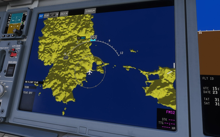
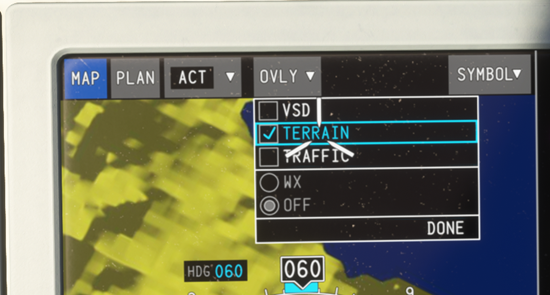
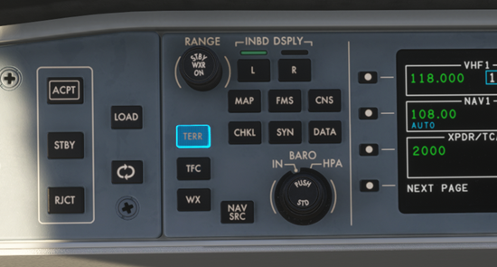
The Synaptic A220 Navigation Display (ND) supports a highly detailed terrain map overlay that accurately simulates the various rendering behaviours of the real unit. This relies on data injection from a separate map-server app running alongside the sim. App InstallationFollow the instructions at https://docs.synapticsim.com/pilots/map-server to install the map server. Enabling Terrain Overlay on NDVia Dropdown Select the OVLY dropdown on the ND Tick the TERRAIN checkbox Via TERR Button Ensure MAP is displayed on atleast one INBD Display. Press the TERR button on the glareshield on either side of the cockpit.
-
Download the A220 Paintkit using the link below: Synaptic A220 Paintkit_1.0.1.zip V1.0.1 Changelog: Blender file is sectioned per texture material now Added wing reg decals Added Comp textures to all PSDs Added readme file
-
Download the attached Synaptic x iniBuilds A220 Manual A220_MSFS_Manual_v1.0.0.pdf For more systems information, check out the Synaptic Documentation https://docs.synapticsim.com/
-
The Synaptic A220 comes with a custom GSX Profile bundled in the Marketplace streamed/downloaded package already. However, if you encounter issues with GSX recognizing the aircraft type, you can install the linked GSX profile manually as a backup. Installation Extract the synaptic_a220 folder to %AppData%\Virtuali\Airplanes Uninstallation Delete the synaptic_a220 folder from %AppData%\Virtuali\Airplanes Synaptic A220 GSX Profile.zip
-
A220-300Click the image to add the airframe to your SimBrief!
-
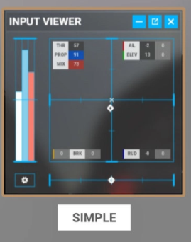
@willwest43 If you have one, that also shows your control inputs simultaneously on screen would be ideal. Also mention the hardware you're using for control. You could use something like the input viewer from your toolbar to show inputs in real time. Enable the "Simple" layout with numbers as well for reference. Thanks!
-
Thanks will pass it on to the team for further evaluation.
-
Yes your submitted reports are under investigation, and any changes are subject to data validation. Changes to engine parameters or cruise pitch angles has effects across all phases of flight. Just to manage expectations don't expect a quick turnaround on this. Things you mentioned falling back on your legacy FSX knowledge are not directly applicable to how things work in MSFS24. (e.g. Table 1506 etc.) Thanks for your patience meanwhile!
-
Thanks will pass it on to the team.


