


richboy2307
-
Posts
1706 -
Joined
-
Last visited
-
Days Won
83
Content Type
Profiles
Forums
Downloads
Posts posted by richboy2307
-
-

The iniBuilds A340 Airliner EFB allows you to plan your entire flight, from departure to arrival, right from the cockpit using the EFB Flight Planner page.
Accessing the Flight Planner
The new planner has its own dedicated page which can be found on the EFB Dispatch section.
(Click to enlarge image)QuoteNote: You must connect to your Navigraph account & enter your Simbrief User ID (numbers only) on the EFB 3rd Party Settings page in order to use this functionality.
(Click to enlarge image)Creating a SimBrief Flightplan via the Planner
In order to create your flight plan, only the following fields are mandatory
- FROM* - Input your Departure airport's 4-letter ICAO code here (e.g. LPFR)
- TO* - Input your Arrival airport's 4-letter ICAO code here (e.g. EGLL)
Then, press the GENERATE PLAN button to create a SimBrief Flightplan using the default "AUTO" values.
(Click to enlarge image)For additional customization, you can also tweak the below fields which are optional
- ALTN -Set your alternates plan here or input their ICAO codes manually. Default value is AUTO.
- AIRLINE - Input any 3-letter ICAO airline code (e.g. AFR)
- FLT NUM - Input any alpha-numeric flight numer (e.g. 25A)
- FROM RWY - Select your Departure airport's desired runway. Default value is AUTO.
- TO RWY - Select your Arrival airport's desired runway. Default value is AUTO.
- PAX - Input the number of desired passengers. Values exceeding the MAX will use MAX instead. Default value is AUTO.
- FREIGHT - Input the desired weight (KG/LBS) of cargo. Values exceeding the MAX will use MAX instead. Default value is AUTO.
- CRZ FL - Enter your desired Cruise altitude in 3-digit flight levels (e.g. 380 for 38,000ft). Default value is AUTO.
- REG - Enter your desired aircraft registration.
- CPT NAME - Input custom Captain's Name on the OFP. Default value is AUTO.
- FO NAME - Input custom First Officer's Name on the OFP. Default value is AUTO.
- PLAN - Choose the desired OFP format from the list that shows on screen. Default value is LIDO.
- FUELING section - Choose between WEIGHT or MIN units and enter the desired numeric value for that particular fuel section on your OFP. Default value is AUTO.
To reset the page back to its default state, click the CLEAR button.
(Click to enlarge image)To change the planning units between KG/LBS, change the Aircraft Weight Units from the EFB Aircraft Settings page.
(Click to enlarge image)Using your New Flightplan - OFP
Once you have successfully generated a flight plan, the EFB will automatically go to the OFP page and give you a 'PLAN GENERATED SUCCESSFULLY' notification at the top of the screen. That's it! Your new flightplan is now active on SimBrief, same as if you had generated via their Dispatcher Tool or Website.
Now you may use this new plan on the MY FLIGHT, PAYLOAD & FUELING, TAKEOFF PERF or LANDING PERF pages of the EFB by Importing or syncing with Simbrief as usual. You may also request your new flightplan on the FMS via the INIT REQUEST* button on the INIT A Page.
-
The iniBuilds A340 Airliner offers customizable GSX integration through the Electronic Flight Bag (EFB), enabling you to control and set the level of service automation provided by GSX. Note that GSX Aircraft Profiles are not required as they come included with the airplane.
(Click to enlarge image)Setup - GSX Options Page
The EFB GSX Options page allows you to enable integration, service notifications as well as manipulate the GSX menu and setup the desired level of service automations. We will go over the functionality of each of the options on this page below.
GSX OPTIONS- INTEGRATION: Toggles GSX Integration & Remote Menu for access within the EFB
- SERVICE NOTIFICATIONS: Toggles the visibility of GSX notifications at the top of the EFB display
-
AUTO IMPORT SIMBRIEF: Toggles the automatic import of your latest Simbrief OFP Data for GSX Loading
Note: Requires you to enter your Simbrief User ID in GSX Settings as well as on the EFB 3rd Party Settings.
GSX MENU
- TOGGLE MENU: Toggles the visibility of GSX Remote menu as long as the INTEGRATION is set to ON.
- GSX REMOTE MENU: The menu is shown here to allow GSX Services control via the EFB
SERVICE AUTOMATION
- GPU CONNECTION: Toggles automatic GPU availability on gate arrival.
- CHOCKS: Toggles automatic Chocks availability on gate arrival.
- CATERING: Toggles automatic request of Catering services when using LOAD WITH GSX on the EFB Payload & Fueling page.
- REFUELING: Toggles automatic request of Refuelling services when using LOAD WITH GSX on the EFB Payload & Fueling page.
- PUSHBACK: Toggles automatic request of Pushback services when using LOAD WITH GSX on the EFB Payload & Fueling page.
- DEBOARDING: Toggles automatic request of Deboarding on gate arrival.
- JETWAYS: Toggles automatic request of Jetways on gate arrival.
(Click to enlarge image)Operation - Load with GSX
To Load with GSX,
- Ensure INTEGRATION is set to ON on the GSX Options Page.
- Press the IMPORT ALL FROM SIMBRIEF button on the EFB Payload & Fueling page.
- Wait for the PLAN fields to update with your Simbrief OFP values.
-
Press LOAD WITH GSX button.
Quote
Note: Depending on your Service Automation settings on the GSX Options page, this will trigger Boarding and other relevant services. In case GSX fails to sequence its services properly, please manually request the service via GSX Remote Menu on the EFB GSX Options page.
QuoteNote: In case you notice any discrepancies between your PLAN vs LIVE weight values after GSX services are completed, please ensure your PLAN values are correct and then press INSTANT LOAD button to ensure the correct weights are set immediately.
These discrepancies can sometimes arise due to the way GSX COUATL interacts with the sim WASM. Our team is actively looking into workarounds to to improve reliability of this process.
(Click to enlarge image)
Operation - Manual Service Request
You may also request individual services manually via the GSX Remote Menu on the EFB GSX Options page, however note this may not update the aircraft Fuel & Payload values correctly. You may need to manually load the aircraft after GSX boarding/refuelling is completed in such instances.
For more information on manual loading, please see How to - Fuel & Payload Management FAQ.
-
What is WASM?
The WebAssembly Module (WASM) is a container for running programmes written in other langauges (eg C/C++) that is then converted to native code ahead of time (as DLLs) during first launch (WASM Compilation). This helps improve performance for subsequent uses but causes longer load times on first launch. See for more info:
This improves security of the sim and portability of projects across PC/Xbox. In case of issues, only the WASM crashes instead of the rest of the sim along side with it. This is why the sim and some functions may continue to work, however other systems and displays that use WASM on the aircraft become unresponsive or "freeze" in place.
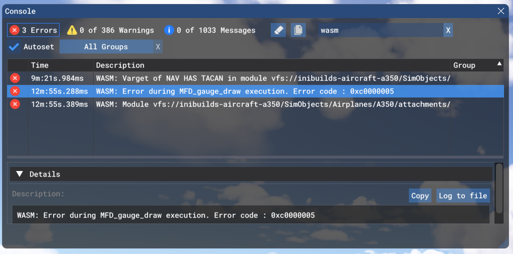
So what to do in case of WASM crash?- Do not close the sim/restart flight immediately
- Verify the WASM error message
- Report the WASM error message with reproduction steps using the guide below.
Verify WASM Crash in Sim
Step 1. Enable Developer Mode
(FS24) Settings > General > Advanced OptionsStep 2. Enable the Console by pressing "~" key on your keyboard or using the Dev Toolbar at the top of the screen
Step 3. Filter the Console by ❌Error messages only by clicking on ⚠️Warning and ℹ️Messages to disable them
(remove blue box border around them).Step 4. Type 'WASM' in the search box. Find the WASM Error and Copy the message. Also take a screenshot of this console window for making a report.
Report WASM Crash on Forum
Step 5. Paste the WASM Error message and screenshot of the Console obtained in Step 4 above into a forum post WASM Crash Report.
Step 6. Take note of what you pressed or things you did, just before you noticed this crash happen.
Step 7. Verify if you are able to repeat the crash by following those same steps.
Step 8. Please provide the following information
- Aircraft: A340 EIS 1 or EIS 2 + Passenger / VIP / Freighter
- Simulator: FS2024
- Version: Update Version and Source (Marketplace / iniManager)
- Navdata Method: SIM DEFAULT or NAVIGRAPH
- OFP: Include a PDF of your Operational Flightplan (OFP) if related to FMS/Route Procedures crashes
- WASM Error: The error you copied in Step 4 above
- Specs: CPU, GPU and RAM of your system.
- Autosave File: Please include the latest ".bin" autosave file prior to your crash.
Step 9. Where possible, include on your report
- a Screenshot / Video showing what you pressed/did just before the crash happened to give us more clues.
- steps on how to reproduce the crash so that we can try ourselves with debugging tools to identify the cause of crash.
-
The Autosave File, include the latest ".bin" autosave file prior to your crash to help us reload into same scenario.
FS24 Autosave Folder Paths
- Steam: %APPDATA%\Microsoft Flight Simulator 2024\WASM\MSFS2024\inibuilds-aircraft-a340\work\autosaves
- MS Store: %LOCALAPPDATA%\Packages\Microsoft.Limitless_8wekyb3d8bbwe\LocalState\WASM\MSFS2024\inibuilds-aircraft-a340\work\autosaves
These types of WASM crashes are actionable depending on your reports of the steps taken immediately before the crash happened. If reproducible on our end by following the same steps, can be debugged and resolved more efficiently.
QuoteExample WASM Crash Report
I had this WASM crash when I clicked the VIDEO button on the center pedestal.
To reproduce
- Load at gate
- Power on aircraft (Battery, GPU)
- Click VIDEO button
- Systems freeze
Information
- Aircraft: A340 EIS1 Passenger
- Simulator: FS2024
- Version: v1.0 from Marketplace
- Navdata Method: NAVIGRAPH
- OFP: Not required, happens on any route
- Specs: Ryzen 5800X, RTX 3070, 16GB RAM
- Autosave: Attached latest .BIN file before crash
- WASM: Error during MFD_gauge_draw execution. Error code : 0xc0000005
-
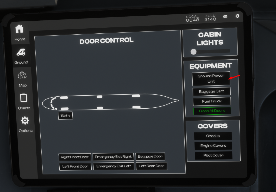
In MSFS 2024, 'Preflight Walkaround' is the first phase of a flight when you start 'cold and dark' from a parking spot / ramp. Your pilot character spawns close to the currently selected aircraft, and it is possible to walk around and interact with various doors, panels and hatches.
Exiting Walkaround
You may exit the pre-flight walkaround at any time by clicking on the door handle or using the user-defined key bind for 'TAKE CONTROL OF CHARACTER' (Default: Shift+C).
Control Settings - Keybind for Entering/Exiting 'Preflight' mode
Walkaround Operables
On the iniBuilds A340 Airliner for MSFS 2024 there are a few doors, hatches or panels that open conditionally or via interactions in this mode:
-
Air Conditioning Panel Door - Connects Air Conditioning Unit (ACU) and Hoses
-
Ground Air Conditioning Engine Starting Panel Door - Connects Air Starter Unit (ASU) and Hoses
-
Ground Electrical Panel Door - Connects GPU and cables
-
Ground Chocks - Connects NLG and MLG chocks
-
Waste Water Service Panel Door
-
Potable Water Panel Door
-
AFT Cargo Door Operation Panel Door
-
FWD Cargo Door Operation Panel Door
-
Refuelling Electric Control Panel Door
-
Gear Door Panel & Levers (Center, Left, Right Main) - Pull to release doors, pressurise hydraulic ELEC pumps to retract doors.
-
Engine Cowling Hatches - Press to Open/Close each engine's cowlings
-
Air Conditioning Panel Door - Connects Air Conditioning Unit (ACU) and Hoses
-
The iniBuilds A340 Airliner FMS features D-ATIS requests for any online station on VATSIM / IVAO / PilotEdge via the Hoppie Network through the ATSU Datalink function.
Setup - Connect to Hoppie Network
The D-ATIS requests are processed through the Hoppie Network so require you to setup your Hoppie Logon Code on the EFB 3rd Party settings page. If you are a new user, you can register for a free Hoppie Logon code here: https://www.hoppie.nl/acars/system/register.html
Once you have your code, you can enter this manually via the On-Screen Keyboard OR by pasting it into the field by clicking on the text field and then pressing Cntrl+V key on your keyboard.
(Click to enlarge image)Operation - D-ATIS Request
To request D-ATIS,
- Ensure the FMS INIT A page FROM/TO and FLT NBR fields are filled in.
-
Access the ATC MENU page on the FMS via ATC COMM > ATC MENU > -> (Next Page) > ATIS
-
Type in the ICAO IDENT for your desired airport in the ARPT/TYPE field.
QuoteNote: In case the station has a separate Departure (_D) and Arrival (_A) ATIS available, you can request it specifically by entering ICAO/DEP or ICAO/ARR instead (E.g. OMDB/DEP or OMDB/ARR)
- Choose ATIS TYPE to request from VATSIM / IVAO / PILOT EDGE as desired by clicking the L5 LSK
- Set PRINT to AUTO (default) or MANUAL by clicking the R6 LSK
-
Press REQ SEND* by clicking the respective R1 to R4 LSK
- By default the D-ATIS will print automatically.
- To review the message on the FMS, access the AOC RCVD MSGS page via ATC COMM > AOC MENU > RCVD MSGS
(Click to enlarge image)QuoteNote: The FMS INIT A page FROM/TO field need to be filled, along with your FLT NBR, for the Network to identify which station to send the requested data back to.
-
The iniBuilds A340 Airliner FMS features METAR/TAF requests for any airport via the Hoppie Network through the AOC WX REQUEST function.
(Click to enlage image)Setup - Connect to Hoppie Network
The AOC WX Requests are processed through the Hoppie Network so require you to setup your Hoppie Logon Code on the EFB 3rd Party settings page. If you are a new user, you can register for a free Hoppie Logon code here: https://www.hoppie.nl/acars/system/register.html
Once you have your code, you can enter this manually via the On-Screen Keyboard OR by pasting it into the field by clicking on the text field and then pressing Cntrl+V key on your keyboard.
Operation - FMS AOC WX REQUEST
To request weather,
- Ensure the FMS INIT A page FROM/TO and FLT NBR fields are filled in.
- Access the AOC WX REQUEST page on the FMS via ATC COMM > AOC MENU > WX
- Type in the ICAO IDENT for your desired airport
- Choose <Y> for METAR or TAF as desired by clicking the L2 or L3 LSK respectively.
- Press *SEND by clicking the R6 LSK
- The AOC RCVD MSGS page will open automatically. Open the latest <WEATHER message to see your requested information.
- To review the message again later, access the AOC RCVD MSGS page on the FMS via ATC COMM > AOC MENU > RCVD MSGS
QuoteNote: The FMS INIT A page FROM/TO field need to be filled, along with your FLT NBR, for the Network to identify which station to send the requested data back to.
-
The iniBuilds A340 Airliner features the option to automatically pause your simulator at a user customizable distance prior to your Top of Descent (TOD) pseudo waypoint. This is useful for when you intend to leave you simulator unsupervised but do not wish to miss out the fun of descending into your destination.
(Click to enlarge image)EFB Pause at TOD Option
You can enable the option to automatically Pause at TOD from the EFB Aircraft Settings page. Here you can also set the custom distance (in NM) for when before your TOD waypoint you want this pause to engage.
(Click to enlarge image)EFB Resuming Flight after Pause at TOD
Once the Pause at TOD engages, you will see a SIM PAUSED message in red at the top of your PFD.
Additionally you will see a 'TOP OF DESCENT PAUSE' notification on the EFB. To resume your flight, simply press the 'RESUME FLIGHT' button on the EFB.
(Click to enlarge image) -
The iniBuilds A340 airliner features upto 4x time compression which can be enabled via the Electronic Flight Bag (EFB). This feature increases the simulation rate by upto 4x to allow you to conduct your flights faster, however it may come with a performance penalty depending on your hardware.
EFB Time Compression Settings
The Time Compression controls are in the EFB quick menu which is accessed via the cog at the top right corner of the EFB. Here you can choose between various options as follows
- DISABLED - disables time compression instantly
- MAX 2X - enables 2x time compression
- MAX 4X - enables 4x (or 2x) time compression
The time compression is automatically disabled or downgraded in the following conditions
- Autopilot is disengaged
- Aircraft is above 80N (automatically downgraded to MAX 2X)
- Sim Pause at Top of Descent is triggered
(Click to enlarge image)Current Simulation Rate Indicator
The current simulation rate is shown on the EFB Quick Menu and also in green at the top of the EFB display when time compression is active.
or Pitch/Roll Oscillations during Time Compression
As the time compression feature increases the simulation rate, this also increases the CPU/GPU resource usage in tandem. Results will vary depending on your hardware and sim settings, however in some situations you may observe oscillations in the Pitch/Roll axis due to the performance degradation.
If you are experiencing this regularly, please consider the following
- Use a lower time compression rate (e.g. MAX 2X)
- Lower sim settings that affect CPU usage such as Object and Terrain LOD, glass cockpit refresh rate, off-screen terrain pre-caching or ground/air/sea traffic density.
- Lower sim settings that affect GPU usage such as Raytraced Shadows, Volumetric Clouds, Texture Resolution.
- Set Turbulence to "LOW" under the sim Assistances settings
- Temporarily disable any addons during time compression that may affect flight physics (e.g. RealTurb, FSRealistic etc.)
-
 1
1
-
The FMS in the iniBuilds A340 airliner supports step climbs which can be setup manually or imported automatically from your Simbrief OFP. Additionally, these step climbs can be initiated manually or automatically at the pre-defined waypoints. Both the setup and operation will be discussed in more detail below.
(Click to enlarge image)Accessing FMS Step Alts Page
The desired Step Climbs can be entered manually or imported directly into the FMS STEP ALTS. There are 2 ways to access this page:
-
Via PERF > CRZ page
-
Via F-PLN > VERT REV page of any waypoint that is beyond your Top of Climb (T/C) pseudo waypoint
QuoteNote: The INIT B Page, ZFW and BLOCK fields, need to be populated first in order for the T/C waypoint to be calculated.
Setup - Manual Entry
The desired step altitude can be entered on the FMS STEP ALTS page in the 'WAYPOINT/ALT' format (e.g. ARKIN/330 or ARKIN/33000)
Setup - Auto Import via Simbrief
The step climbs can be automatically imported onto the FMS STEP ALTS page along with your flightplan from Simbrief as long as the following conditions are satisfied:
- A valid SIMBRIEF USER ID (Numbers only) is set via the EFB Settings > 3rd Party Settings page.
- The AUTO IMPORT STEP CLIMB option is enabled via the EFB Settings > Aircraft Settings page.
- The INIT REQUEST* button is pressed to import a flightplan on the FMS INIT A page.
(Click to enlarge image)Operation - Automatic Step Climb
The step climbs entered on the FMS STEP ALTS page will be conducted automatically as long as the following conditions are satisfied:
- The AUTO STEP CLIMB option is enabled via the EFB Settings > Aircraft Settings page.
- The FMS STEP ALTS page is filled with target WAYPOINT/STEP ALT information
-
The target step altitude is not above the REC MAX altitude computed at the time of reaching target waypoint
(else step will be deleted and ignored)
(Click to enlarge image)
(Click to enlarge image)QuoteNote: It is recommended to disable the AUTO STEP CLIMB option whilst flying in controlled airspace on online networks to avoid inadvertent pilot deviation.
Operation - Manual Step Climb
When you are approaching your target step climb waypoint, you will receive a STEP AHEAD message on the FMS. At this point, verify that the target altitude is below your currently computed REC MAX altitude which is found on the FMS PROG page.
To initiate the step, simply dial in your target step altitude on the FCU ALT window, then push the ALT knob to initiate a managed climb. The FMS CRZ FL will also update to the target altitude.
-
Via PERF > CRZ page
-
The iniBuilds A340 airliner features integrated snow and icing effects on the wings, fuselage, and horizontal stabilizer. These effects can develop dynamically over time depending on the type and rate of precipitation, or can be manually adjusted for visual impact through the EFB, functioning as a standalone feature.
(Click to enlarge image)Dynamic Snow Accumulation & Removal
The snow layer forms over the aircraft when you spawn in at the gate in a cold and dark state and the weather conditions are met. This layer will dissolve over time as the aircraft is powered up from its cold and dark state leaving only the ice layer underneath.
(Click to enlarge image)Furthermore, if you use FSDreamTeam’s GSX add-on, the snow and icing can be eliminated as part of the de-icing procedure on the ground when required.
(Click to enlarge image)
EFB Snow Accumulation SliderYou can also manually control the various levels of Snow & Ice Accumulation on the EFB Ground page.
(Click to enlarge image) -
On the iniBuilds A340 Airliner you can set the visual dirt and weathering on the aircraft exterior via the Electronic Flight Bag (EFB). This adds affects of weathering around rivets and general dirt/grime over various components of the exterior that is persistent per variant.
(Click to enlarge image)EFB Dirt & Weathering Sliders
You can control the various levels of dirt & weathering on the EFB Ground page.
(Click to enlarge image)Dynamic Weathering
The initial weathering state is set by the EFB Weathering slider and continues to dynamically increase over time. It will be manually "reset" by adjusting the slider.
QuoteNote: The EFB Weathering slider itself does not dynamically move over time. It is only used to set the initial weathering state whenever moved. However you will notice the dirt, grime and weathering of rivets change over time externally.
-
Our autosave feature from the A350 Airliner returns with expanded flexibility to the A340 Airliner. You can set custom save intervals, manually save flight states, rename autosaves, delete autosaves and reload progress at any time - ensuring your long-haul isn’t lost to a power cut or catastrophic failure.
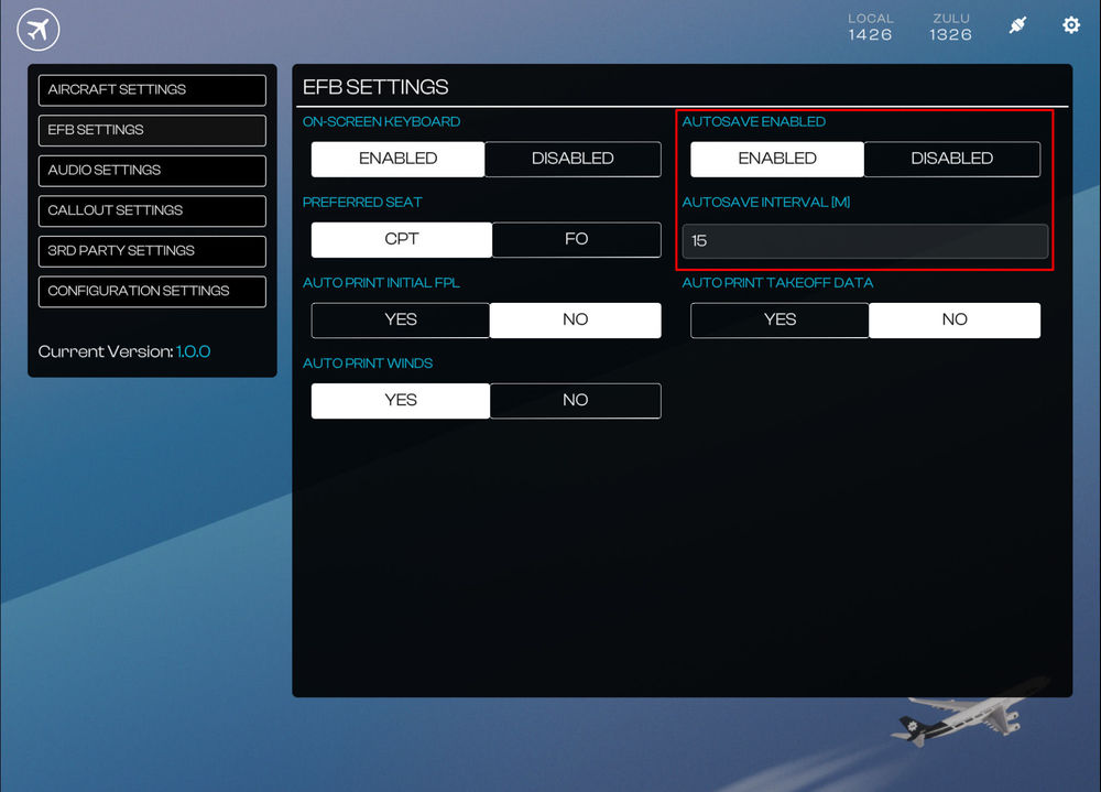
(Click to enlarge image)Autosave Settings
Autosave functionality can be enabled/disabled via the EFB Settings page. You can also set a custom interval (in minutes) on the same page.
(Click to enlarge image)Creating a Custom Saves
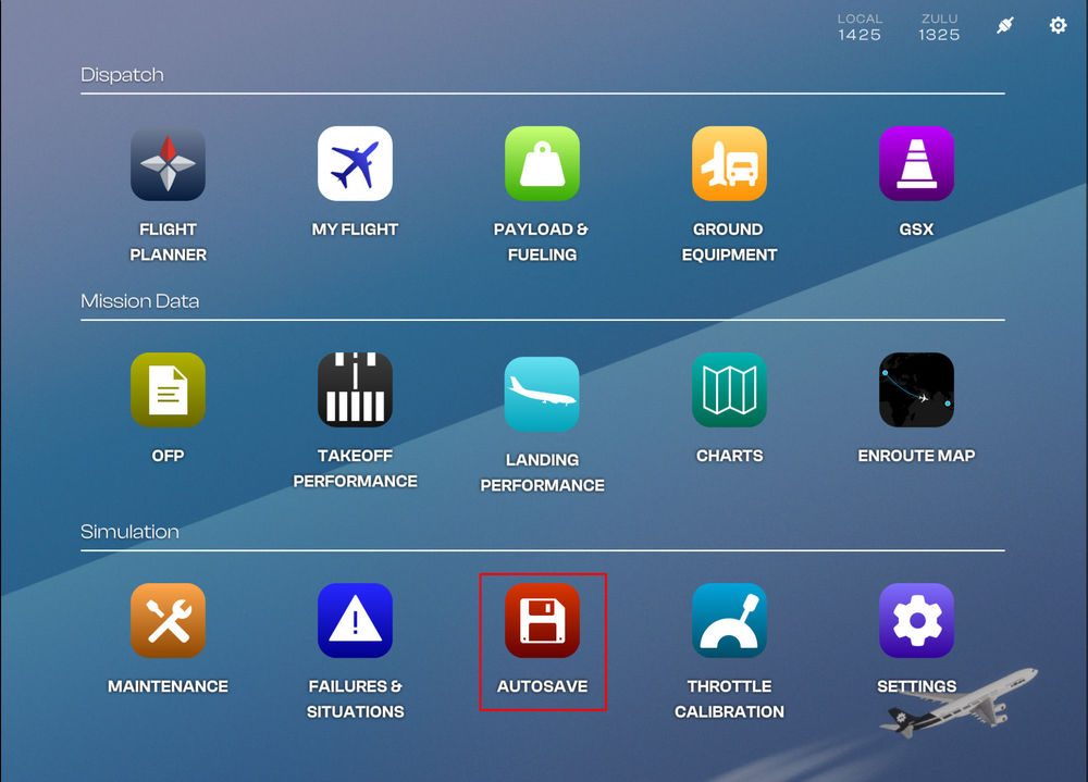
To create a custom save via the EFB:
- Navigate to EFB Autosave Page
- Click 'CREATE SAVE NOW' button
- Enter a desired name for the autosave and then press 'CREATE SAVE' button
- Your custom save will appear on the list on the right side of the page
(Click to enlarge image)Renaming a Custom Save
To rename a custom save via the EFB:
- Navigate to EFB Autosave Page
- Click 'EDIT' button
- Enter the new desired name for the autosave and then press 'RENAME SAVE' button
- Your renamed custom save will appear on the list on the right side of the page
(Click to enlarge image)Deleting a Custom Save
To delete a custom save via the EFB:
- Navigate to EFB Autosave Page
- Click 'DELETE' button
- The custom save will be removed from the list on the right side of the page
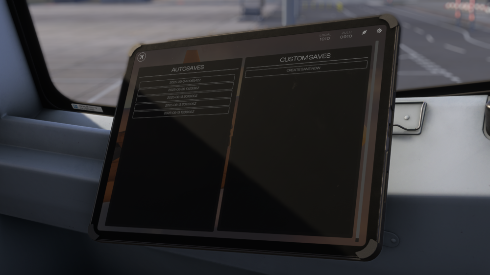
(Click to enlarge image)Loading Custom / Auto saves
To load any custom/auto save via the EFB:
- Navigate to EFB Autosave Page
- Click the desired save from the AUTOSAVES or CUSTOM SAVES list.
- The sim may take a few seconds to load the proper panel states after teleporting you to save location.
(Click to enlarge image)Sharing Custom Saves
All custom and auto saves are stored as ".bin" files in your WASM/work folder. These can be shared with other users or our staff for support requests. Simply drop the save files in the folders listed below and then reload the OIS autosave page to see it on the list.
The autosaves folder is found at the various paths listed below:
QuoteFS24 Steam:
%APPDATA%\Microsoft Flight Simulator 2024\WASM\MSFS2024\inibuilds-aircraft-a340\work\autosaves
FS24 MS Store:
%LOCALAPPDATA%\Packages\Microsoft.Limitless_8wekyb3d8bbwe\LocalState\WASM\MSFS2024\inibuilds-aircraft-a340\work\autosaves
(Click to enlarge image) -
The iniBuilds A340 Airliner comes with various aircraft configuration options that you can toggle via the EFB Configuration Settings page.
Configuration Options
The following configurations are available
-
SATCOM
-
ICE DETECTOR
-
BRAKE FANS
-
STANDBY INSTRUMENTS (ANALOG / ISIS) - EIS 1 Only
-
Para Visual Indicator (PVI) - EIS 1 Only
-
SATCOM
-
The iniBuilds A340 Airliner EFB Charts app supports both sim default LIDO and Navigraph charts in MSFS 2024. You can swap between the two via the EFB 3rd Party Settings Page.
(Click to enlarge image)QuoteNote: Use of Navigraph Charts requires an active Navigraph Ultimate subscription.
Connecting to Navigraph
- Navigate to Settings > 3rd Party Settings > Navigraph Login section on the EFB
- Scan the QR Code or click the 'OPEN BROWSER' button to connect your Navigraph account
- After you have completed the authentication steps, the EFB will update to show some new options - LOGOUT OF NAVIGRAPH and UPDATE NAVDATA along with the currently installed cycle.
-
The iniBuilds A340 Airliner allows you to choose between 'SIM DEFAULT' and 'NAVIGRAPH' as navdata sources for the FMS. You can switch between these options through the Electronic Flight Bag (EFB) on the 3rd Party Settings page.
(Click to enlarge image)The internal 'SIM DEFAULT' navdata is the default option, similar to all our previous airliners for MSFS - which means it will update whenever the sim navdata is updated by Microsoft.
If you swap to the 'NAVIGRAPH' navdata option, the default cycle is 2303 R1. Users with an active Navigraph subscription can update to the latest navdata version by linking their account through the EFB
QuoteNote: Changing navdata source will completely wipe the FMS data. You should only do this prior to completing your FMS preparation as a result.
Connecting to Navigraph
- Navigate to Settings > 3rd Party Settings > Navigraph Login section on the EFB
- Scan the QR Code or click the 'OPEN BROWSER' button to connect your Navigraph account
- After you have completed the authentication steps, the EFB will update to show some new options - LOGOUT OF NAVIGRAPH and UPDATE NAVDATA along with the currently installed cycle.
Updating the Navigraph Navdata
- Click the 'UPDATE NAVDATA' button
- The button will change into a progress bar once download commences.
- Once completed, the button will show 'NAVDATA DOWNLOADED' and the currently installed cycle will update to the latest available.
QuoteNote: This can ONLY be done on the ground without the engines running. This process requires an active internet connection and may take a few minutes whilst the data is downloaded from the servers.
QuoteNote: Updating navigraph navdata will completely wipe the FMS data. You should only do this prior to completing your FMS preparation as a result.
-
Troubleshooting
You may delete your Terrain Database file (iniTerrainV2.bin) manually and then re-download it via the EFB in case you experience any issues.
The file is located in the WASM/Work folder at the path below depending on where you purchased your simulator:
QuoteSteam: %APPDATA%\Microsoft Flight Simulator 2024\WASM\MSFS2024\inibuilds-aircraft-a340\work\
MS Store: %LOCALAPPDATA%\Packages\Microsoft.Limitless_8wekyb3d8bbwe\LocalState\WASM\MSFS2024\inibuilds-aircraft-a340\work\AV False-Flags
Certain antivirus software like MS Defender may falsely flag the Terrain Database file (iniTerrainV2.bin) for quarantine. In case you have any issues, please add an exclusion for the following folders:
QuoteSteam: %APPDATA%\Microsoft Flight Simulator 2024\
MS Store: %LOCALAPPDATA%\Packages\Microsoft.Limitless_8wekyb3d8bbwe\LocalState\ -
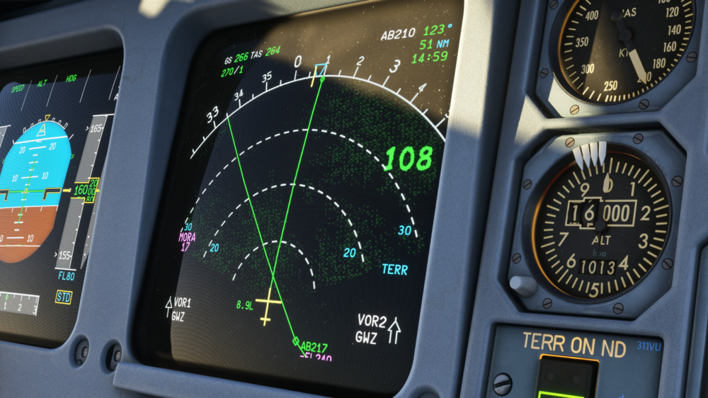
The Navigation Display (ND) on the iniBuilds A340 Airliner can display terrain and obstacles information when the TERR ON ND pushbutton is pressed. This function relies on a Terrain Database which is downloadable via the Electronic Flight Bag (EFB) - 3RD PARTY SETTINGS page.
(Click to enlarge image)Why is this required?
- This process helps ensure terrain data integrity by minimizing risk of corruption whilst streaming the package.
- This process reduces overall bandwidth usage whilst streaming the package.
When is this required?
- This process only needs to be done once when you first launch he A340 Airliner after your purchase.
- The process does not need to be repeated for each variant, as the database is shared between EIS1 and EIS2.
- The process does not need to be repeated when updating the aircraft - unless stated specifically in the changelog.
- The process is only required again IF you manually delete your Terrain database (.bin) file which is located within the WASM/Work folder.
QuoteNote: Clearing your WASM/work folder will also delete the Terrain database file. You will need to repeat the process in that instance.
How to download terrain data?
- Navigate to the Settings > 3rd Party Settings > Download Terrain Data section on the EFB
- Press the DOWNLOAD button and wait for the download to complete.
- Once completed, you will see a notification at the top of the EFB Display.
- Press ESC to return to main menu and restart your flight for the changes to take effect properly.
QuoteNote: The Terrain database (.bin) file is 285 MB in full which is downloaded in two parts. These are automatically combined into a single file at the end. Please be patient and allow some time for the process to complete.
On a 100mpbs connection, the process is usually completed within 60s.
QuoteNote: The sim may freeze during the process as data is transferred within the sim Virtual File System (VFS). Please be patient and allow some time for the process to complete.
(Click to enlarge image) -
Payload & Fueling Page (EFB)
Before you fly, you must set your Zero Fuel Weight (ZFW) and Fuel Load (FUEL) via the Electronic Flight Bag (EFB) - Payload & Fueling Page. You can set these weights manually or import them through Simbrief for instant loading onto the aircraft. Both methods will be explained below.For loading with GSX, please refer to the 'How to - GSX Integration - Setup & Operation' page instead.
(Click to enlarge image)
(Click to enlarge image)Side Panel
Dedicated buttons on the side panel function as follows:
- PAYLOAD: Switches to the Payload Page
- FUELING: Switches to the Fueling Page
-
IMPORT ALL FROM SIMBRIEF: Autofills all fields on the Payload & Fueling page with values from your Simbrief OFP
Note: Requires SB User ID to be set on the Settings - 3rd Party Settings Page first. - GSX OPTIONS: Opens the GSX Options page
- INSTANT LOAD: Loads the set Payload & Fuel instantly
-
LOAD WITH GSX: Loads the Simbrief OFP Payload & Fuel through GSX
Note: Requires GSX Integration to be enabled in the GSX Options first.
The Summary section shows the following:
- MACZFW: Current Center of Gravity (CG) positions shown as a % of MAC that refers to the CG at curent Zero Fuel Weight.
- MACGW: Current Center of Gravity (CG) positions shown as a % of MAC that refers to the CG at current Gross Weight.
- ZFW: Zero Fuel Weight - Planned (PLAN) vs Current (LIVE) in the chosen weight measurement units (LBS/KG).
- PLD: Payload - Planned (PLAN) vs Current (LIVE) in the chosen weight measurement units (LBS/KG).
- FUEL: Fuel - Planned (PLAN) vs Current (LIVE) in the chosen weight measurement units (LBS/KG).
- TOW: Take-Off Weight - Planned (PLAN) vs Current (LIVE) in the chosen weight measurement units (x1000 LBS/KG).
Changing Weight Measurement Units (LBS / KGS)
The aircraft weight measurement units (LBS / KGS) are changed on the EFB Aircraft Settings Page which can be reached via SETTINGS > AIRCRAFT SETTINGS > WEIGHT UNITS. Select your desired unit by clicking on its respective button.
QuoteNote: Changing units will clear all weights from the FMS and can affect VNAV calculations, so you should only change these units whilst on the ground or whenever safe to do so.
(Click to enlarge image)Manual Entry - Instant Loading
- PAYLOAD: Click the PAYLOAD button and then use the On-Screen Keyboard to enter the desired value into the ZFW field.
- FUELING: Click the FUELING button and then use the Slider or On-Screen Keyboard to enter the desired value.
- INSTANT LOAD: Click the INSTANT LOAD button to apply the entered ZFW and FUEL to the aircraft.
You will see a notification at the top of the EFB display confirming the loading of the aircraft.
QuoteNote: Changing ZFW or FUEL whilst airborne may affect VNAV / Fuel calculations, so you should only change these whilst on the ground or whenever safe to do so.
(Click to enlarge image)Simbrief Import - Instant Loading
-
IMPORT ALL FROM SIMBRIEF: Click the IMPORT ALL FROM SIMBRIEF button to autofill the Payload and Fueling pages with values from your Simbrief OFP
Note: Requires SB User ID on the Settings Page first which is accessed via Settings > 3rd Party Settings > Simbrief User ID. - INSTANT LOAD: Click the INSTANT LOAD button to apply the entered ZFW and FUEL to the aircraft.
You will see a notification at the top of the EFB display confirming the loading of the aircraft.
QuoteNote: Changing ZFW or FUEL whilst airborne may affect VNAV / Fuel calculations, so you should only change these whilst on the ground or whenever safe to do so.
(Click to enlarge image) -
Issues with Calibration
If you experience any issues with the Throttle Calibration process, you may force-reset the calibration on the EFB via either of the following methods:
- PC & Xbox: Press the 'RESET CALIBRATION' button or toggle the 'REVERSERS ON AXIS' option between YES and NO to reset the calibration.
-
PC Only: Delete the 'ThrottleData.ini' file to start fresh on next launch of the simulator. This file will be found in the work folder of the aircraft, and the path will vary based on where you purchased the simulator:
Steam: %APPDATA%\Microsoft Flight Simulator 2024\WASM\MSFS2024\inibuilds-aircraft-a340\work
MS Store: %LOCALAPPDATA%\Packages\Microsoft.Limitless_8wekyb3d8bbwe\LocalState\WASM\MSFS2024\inibuilds-aircraft-a340\work
Issues with Reversers
If you experience any issues with the operation of reversers on hardware with reverse on axis (E.g. TCA Quadrant Airbus Edition), please ensure the following:
- Reverse on Axis: Ensure you have selected YES on the EFB Throttle Calibration page.
- Calibration: Ensure you have completed the calibration at least once. This will ensure the creation of a 'ThrottleData.ini' file.
-
ThrottleData.ini : The file can be found at the path stated above. Open with a text editor (e.g. Notepad) and check that it says the following -
[throttle]
reverse_on_axis = true
If it says false, change it to true as above. Reversers should then work after a sim restart.
-
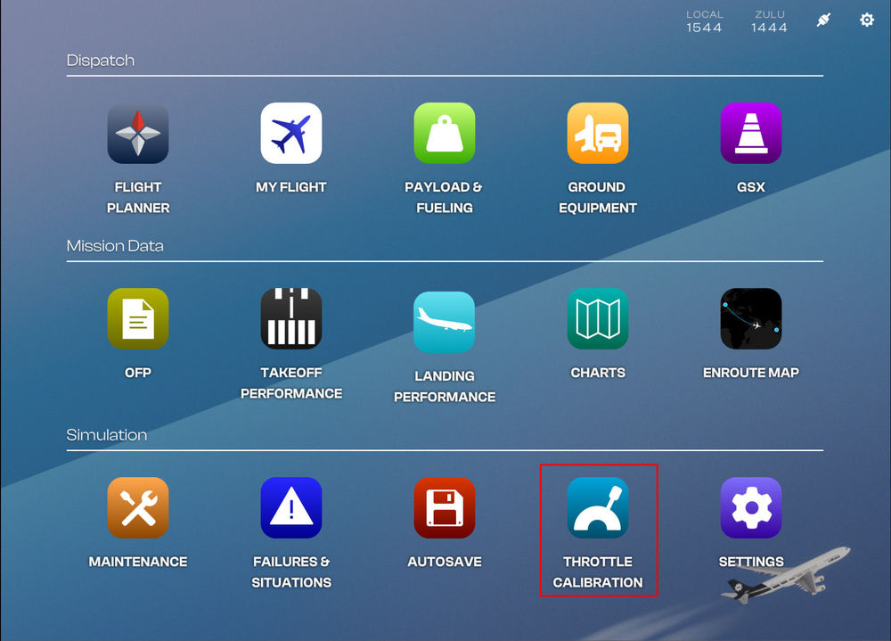
Throttle Calibration Page (EFB)
Before you fly, you must calibrate your throttles via the Electronic Flight Bag (EFB) - Throttle Calibration page.
(Click to enlarge image)QuoteNote: You must assign Throttle Axis 1 to 4 in the MSFS Controls settings to your available hardware axis accordingly. The Throttle Calibration process is not a substitute for control assignment in MSFS Settings. The purpose of calibration is to assign detents and dead zones only.
Throttle Calibration Process
Typically the throttle calibration is done in the following order
- Ensure that Throttle Axis or Throttle Axis 1 to 4 are assigned in the MSFS Control settings.
- Set desired REVERSERS ON AXIS option
- Set desired INPUT AXIS COUNT option
- Set desired INPUT DEADZONE %
- Move your hardware throttle axis to the position you want to define as a detent (e.g. IDLE/CLB/FLX/TOGA)
- Click the SET (DETENT) POSITION button on the EFB to define the current position to the detent chosen
- Observe new detent position shown on the diagram on the right.
-
Repeat Steps 4 to 7 for each desired detent.
QuoteNote: You will have to repeat this process if you want to change INPUT DEADZONE % or REVERSERS ON AXIS option after completing the calibration.
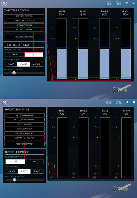
Reversers on Axis Option
Verify whether your hardware has a reverse thrust on an axis or not then choose the appropriate option.
'REVERSERS ON AXIS' is set to NO:
- The bottom most position of your hardware axis (0%) will be assignable to the IDLE detent position.
- You may have to bind 'HOLD' / 'TOGGLE REVERSE THRUST' sim control binding to an additional button / input on your hardware to use reverse thrust.
- This option is recommended for majority of consumer flight simulation hardware (including Xbox Controllers).
'REVERSERS ON AXIS' is set to YES:
- The bottom most position of your hardware axis (0%) will be assignable to the MAX REV detent position for thrust reverser operation.
- You can additionally define separate IDLE and IDLE REV detent positions.
- This option is recommended for hardware such as the TCA Airbus Throttle Quadrant.
(Click to enlarge image)Input Axis Count Option
Verify whether your hardware has One, Two or Four independent axis available for throttle control, then choose the appropriate option. This changes how the calibration values are copied across ENG1 to ENG4.
QuoteNote: This option is not a substitute for control assignment in MSFS Settings. You must still assign Throttle Axis 1 to 4 in the MSFS Controls settings to your available hardware axis accordingly.
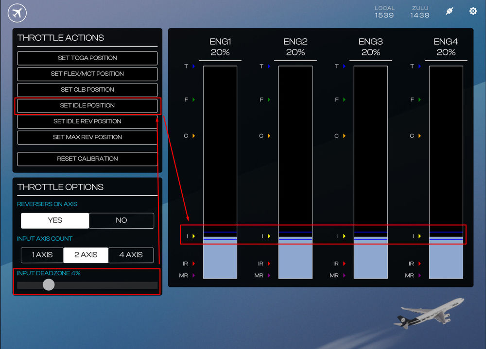
Input Deadzone Option
You may define a Global 'Input Deadzone %' for all detents during the Throttle Calibration Process which we will cover below.
The present deadzone % boundary is also shown visually on the axis diagram to the right via dark blue lines above/below your present AXIS % value. These lines indicate that the assigned detent will activate whenever ENG1 to ENG4 % values are within the two blue lines. The larger the number, the further apart the blue lines will be meaning the the detent is engaged for a larger range of hardware axis movement.
Applying a Deadzone %
- Use the slider to choose the desired 'INPUT DEADZONE %' value (Default is 2.5%).
- Click the SET (DETENT) POSITION button to apply the set value to your detent.
QuoteNote: If you want to change the 'INPUT DEADZONE %' value, you must repeat the Throttle Calibration Process again after setting new value.
Example - Applying a 4% Deadzone to IDLE detent
(Click to enlarge image)Example Throttle Calibration Process
Example #1 - Defining a CLB detent with Reverser On Axis = NO
- Move your hardware axis physically to where you want to define the CLB detent.
- Set your desired 'INPUT DEADZONE %' for the current detent.
- Press the 'SET CLB POSITION' button on the EFB.
- Verify on the diagram on the right a C > appears showing the newly defined CLB detent position, with the relevant % above.
QuoteNote: A 4% Input Deadzone set for a CLB position defined at 69% axis value means that CLB Detent will engage anywhere between 67% to 71% axis value after calibration.
(Click to enlarge image)Example #2 - Defining a Max Reverser detent with Reverser On Axis = YES
- Move your hardware axis physically to where you want to define the MAX REV detent.
- Set your desired 'INPUT DEADZONE %' for the current detent.
- Press the 'SET MAX REV POSITION' button on the EFB.
- Verify on the diagram on the right a MR > appears showing the newly defined MAX REV detent position, with the relevant % above.
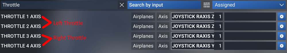
(Click to enlarge image)QuoteNote: TCA Airbus Throttle Quadrant users - for best results, ensure the following
- Assign your left throttle to THROTTLE 1 AXIS and THROTTLE 2 AXIS , and
- Assign your right throttle to THROTTLE 3 AXIS and THROTTLE 4 AXIS
- On the EFB Throttle Calibration app, use 4-Axis Option -
Wolf's Fang Runway
- IATA: WFR
- ICAO: AT98 (recognized via Navigraph Navdata / Simbrief only)
- LID: AT98
- AD Co-ordinates: 71° 31′ S, 08° 48′ E (FMS Format: 7131.0S / 00848.0E)
- AD Elevation: 3725' / 1127m AMSL
- Rwy Length: 8200' / 3000m
- Rwy Width: 196' / 60m
- Rwy Orientation: 175 True (175T)
-
Rwy Declared Distances: TORA AND LDA 2500m / TORA AND ASDA – 3000 m
Common Routes (FACT - AT98)
You may use any of these below on Simbrief for planning purposes- IMSOM UQ36 APKIN UL211F ITLIK 3713S 4112S 4811S 6209S 6808S
- GEPAB 4018S 5016S 5814S 6412S 6810S 7008S
- IMSOM UQ36 APKIN UL211F ITLIK 3615S 4014S 4513S 5013S 5513S 6012S 6511S 7010S
You may also append the following waypoints from the approach segment for the final part of your flightplan as necessary
- 711635S0084411E 712133S0084525E 713034S0084741E
Suggested Approach Custom Waypoints
You may create these custom waypoints in your aircraft FMS for a straight in approach to RWY 17T- IAF: WF17I 7116.6S 00844.2E [220/6900']
- FAF: WF17F 7123.0S 00842.9E [220/6900']
- MAPt: MA17 7130.6S 00847.7E [Vapp / 4300']
- RWY 17T: R17T 7131.0S 00848.0E [3725']
- Go Around WPT: WFM01 7122.0S 00829.9E [185/6900']
(Click to enlarge images)
Note: These are approximate waypoints and will keep you on path but once you have the runway in sight, you should proceed visually.
-
3
-
 1
1
-
 4
4
-
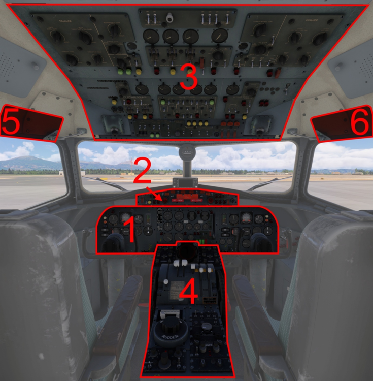
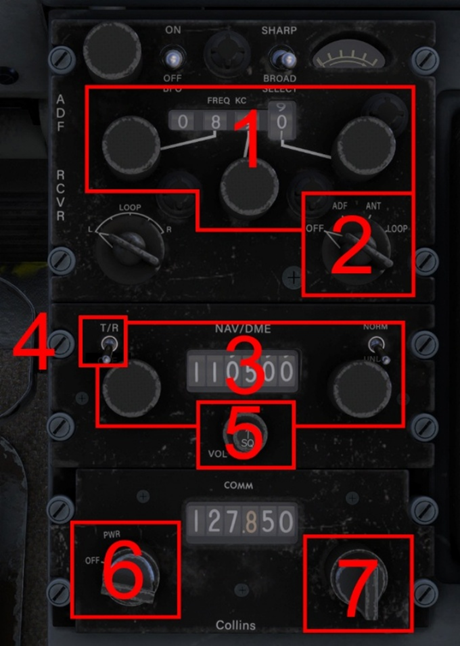
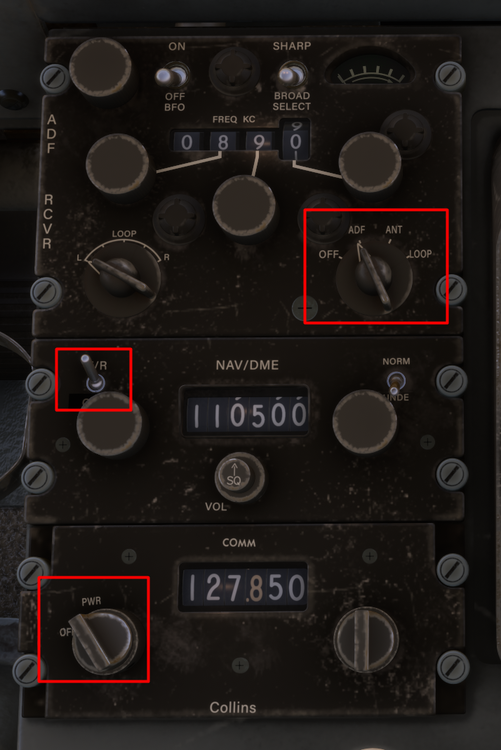
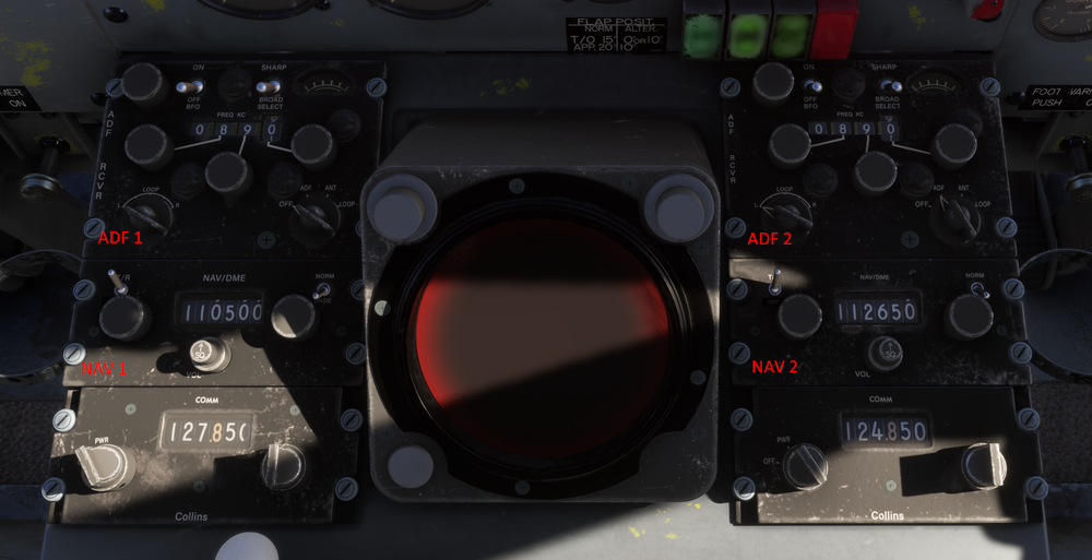
The YS-11 is equipped with 2x COM radios, 2x NAV receivers and 2x ADF Receivers. All of these can be tuned via controls found on the forward section of the Centre Pedestal (4)
Forward Pedestal Radios
- ADF Frequency and Selector Knobs
- ADF Power Switch
- NAV Frequency and Selector Knobs
- NAV Power Switch
- NAV Ident Volume Knob
- COM Power Switch
-
COM Frequency Selector Knobs
QuoteNote: Left and Right-side radios are identical in their operation. Left- side radios control ADF1, NAV1 and COM1.
Right-side radios control ADF2, NAV2, COM2.
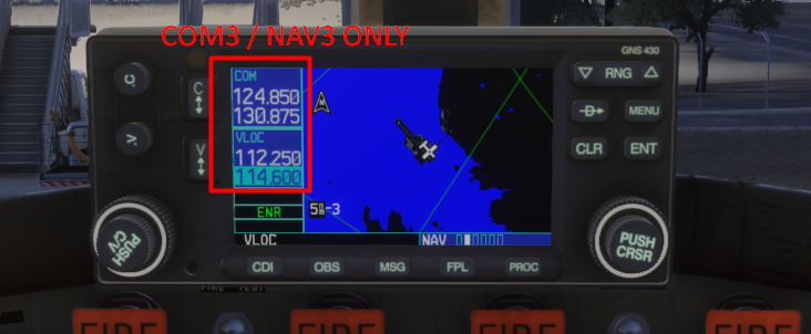
WT GNS430 GPS
If you are using the WT GNS430 GPS, the radio controls on the GPS are tied to COM3 / NAV3 only. Please use the radios on the pedestal only for communication / navigation.QuoteNote: This is by design to avoid conflicts with Classic panel (no GPS) and keep it hot-swappable via the EFB.
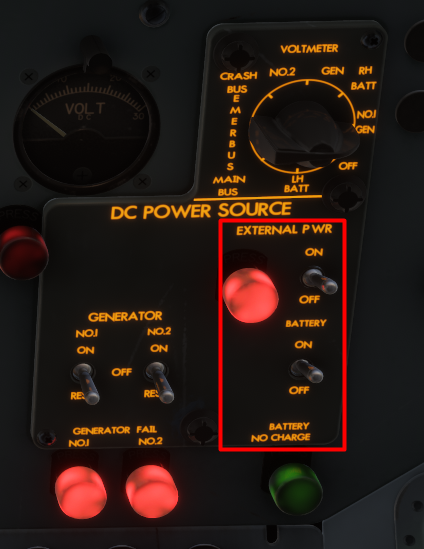
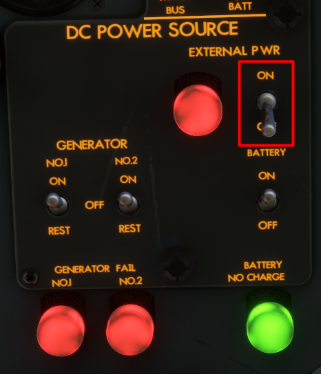
RADIOS - ELECTRICAL POWER
To operate the radios and avionics, proper power source needs to be established, in addition to turning on their respective unit power switches.
To establish electrical power on the ground,
- Turn on BATTERY Switch on the Overhead Panel
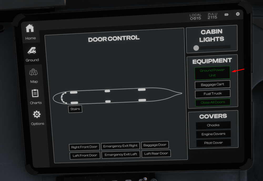
-
Connect External Power via EFB + Turn on EXTERNAL POWER Switch on the Overhead Panel
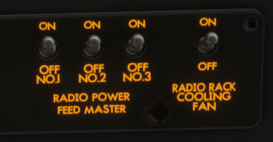
-
Turn on RADIO POWER FEED MASTER No. 1 / 2 / 3 switches on the Overhead Panel
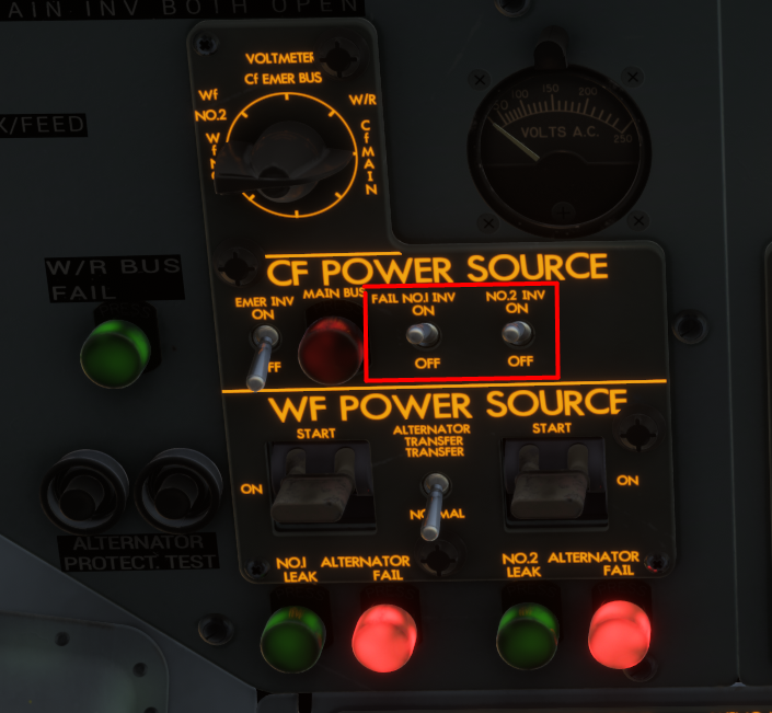
-
Turn on CF POWER - INVERTER SWITCHES NO.1 / 2 on the Overhead Panel
-
Turn on COM / NAV / ADF power switches on the Center Pedestal
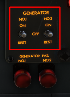
After Engine start,
-
Turn on the GENERATOR NO. 1 / 2 switches on the Overhead panel
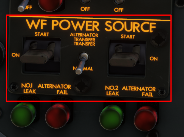
-
Turn on the WF POWER SOURCE - ALTERNATOR NO.1 / 2 switches by moving to START then ON position on the Overhead panel
-
Turn off the EXTERNAL POWER Switch on the Overhead Panel + Disonnect External Power via EFB
-
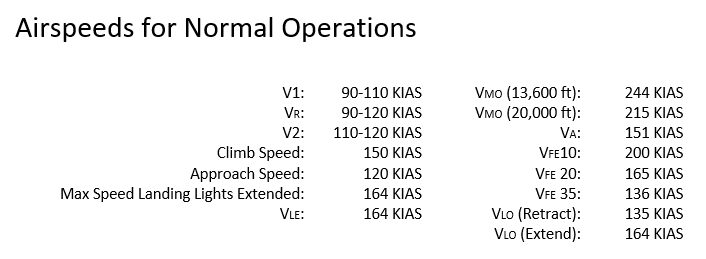
The following section is intended to supplement the Simplified Procedures or in-simulator Checklist. General operating guidelines are provided along with speeds and power settings to be applied per flight phase.
Engine Start
Ensure the Low Stop Lever is in the Ground position. Engine 2 is started first, followed by Engine 1.- Engine 2 HPC lever: ON.
- Starter and Ignition panel: Engine Select No. 2.
- Starter Master: Start.
- Starter Push Button: Push and hold for 4 seconds, the button should remain in.
- When the RPM reaches 1200 to 1500 RPM: Engine 2 HPC lever to HSWL position.
Repeat the procedure for Engine 1.
After Start
Starter and Ignition panel:- Engine Select OFF.
- Starter Master SAFE (middle position).
Set Flap 15, this is the normal Take Off Flap setting.
Take Off
Gently apply full power, note that the Low Stop Lever will automatically move to the Flight position as the power levers are advanced. Full power will be approximately 15,000 RPM.V1 and Vr speed is 90-110 KIAS depending on weight.
Rotate gently, especially at high weights. Allow the aircraft to get airborne on its own and avoid the temptation to increase the pitch further if the aircraft does not become airborne immediately.
Once airborne,
- Adjust your pitch accordingly to maintain a V2 speed of 110-120 KIAS.
- Retract the gear, turn the Landing and Taxi Lights OFF and retract both Landing Lights.
- At 1,000 ft AGL lower the pitch of the aircraft to accelerate. Set 14,200 RPM, retract the flaps.
- Establish a climb speed of 150 KIAS, this will correlate to approximately 1,000 FPM at Maximum Take Off Weight.
Climb
Throughout the climb monitor the speed and adjust the vertical speed accordingly to maintain 150 KIAS.
If using the autopilot remember that there is no altitude preselector in this aircraft. Gently reduce the vertical speed and press ALT to engage altitude hold when your desired altitude is reached.
Cruise
Cruise RPM is the same as climb - 14,200 RPM. Set the HPC levers to the ON position.Monitor your fuel consumption and transfer fuel from the auxiliary tanks to the main tanks as required.
- Engine 1 is fed from Main Tank 1
- Engine 2 is fed from Main Tank 4.
-
Using the transfer pumps, transfer fuel from Auxiliary Tank 2 into Main Tank 1 and from Auxiliary Tank 3 into Main Tank 4.
QuoteNote: VMO reduces with altitude, being as low as 215 KIAS at 20,000 ft. Adjust power accordingly to remain below VMO, this might require less than 14,200 RPM.
Descent
Set power as required to maintain a speed of 200 KIAS. This will correspond to approximately idle power, and a vertical speed of -1,000 to -1,500 FPM.
Approach and Landing
On Approach,- Reduce speed from 200 KIAS to 150 KIAS. Select Flaps 10 when the speed is below VFE.
-
When appropriate (and below VLO of 164 KIAS),
- Extend the landing gear
- Extend the Landing Lights and turn them ON as well
- Turn on the the Taxi Lights.
- Set the HPC levers to HSWL position. - Select Flaps 20 and continue to decelerate to the approach speed of 120 KIAS.
- Select Flaps 35 on final approach whilst maintaining 120 KIAS.
At touchdown,
-
Move the Low Stop Lever to the Ground position.
Note: This lever can be operated using the “Toggle Spoilers” control assignment - Apply brakes as required, remember that the YS-11 does not have reverse.
Go Around
In case of a go around,- Apply Full Power (approx 15,000 RPM).
- Adjust pitch to maintain an initial pitch attitude of 10 degrees.
-
Select Flaps 15.
Note: that when heavy, the YS-11 will take time to accelerate. Monitor the pitch attitude and carefully adjust it to accelerate and prevent altitude loss as the flaps are retracted. - Retract the gear when a positive rate of climb is achieved.
-
At 1,000 ft AGL
- Lower the pitch of the aircraft to accelerate
- Set 14,200 RPM
- Retract the flaps - Establish a climb speed of 150 KIAS, this will correlate to approximately 1,000 FPM at Maximum Take Off Weight.
- Level off at desired altitude and then repeat the Approach and Landing section process.
-
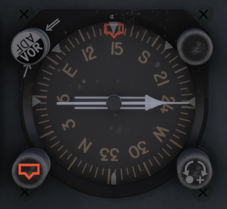
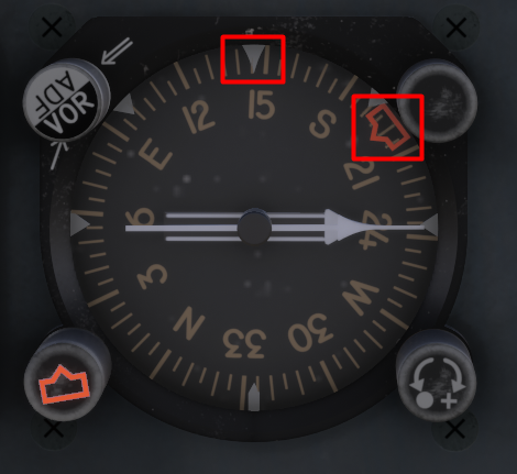
The YS-11 is equipped with a dual-needle Radio Magnetic Indicator (RMI) on each side of the cockpit that is used as both a bearing and heading indicator.
RMI - Bearing Indicator
The two needles always indicate magnetic bearing to the selected beacon (VOR or NDB) provided there is an active signal. The tail of the needle indicates the reciprocal bearing.
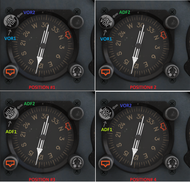
You can configure the needles in a various number of ways using the Selector Knob positions as follows:
- Position #1 - The thin needle (single line) points to VOR1. The thick needle (double line) points to VOR2.
- Position #2 - The thin needle (single line) points to VOR1. The thick needle (double line) points to ADF2.
- Position #3 - The thin needle (single line) points to ADF1. The thick needle (double line) points to ADF2.
- Position #4 - The thin needle (single line) points to ADF1. The thick needle (double line) points to VOR2.
QuoteNote: VOR1 is the VOR frequency you have dialled into NAV 1 receiver. VOR2 is the VOR frequency you have dialled into NAV 2 receiver. ADF1 is the NDB frequency you have dialled into ADF 1 receiver. ADF2 is the NDB frequency you have dialled into the ADF 2 receiver.
RMI - Heading Indicator
The RMI also functions as a heading indicator by using a slaved gyro to always show the direction of the aircraft in relation to magnetic north at the 12 o'clock position.
There is additionally a Heading Selector bug that can be manipulated using the HDG Selector Knob at the bottom left to choose a heading target for the autopilot when using Heading Hold mode.
Example - Current Heading 145 deg,
Selected Heading 200 degFor more information on Autopilot Operation please refer to the manual or see:


 or
or 


Paintkit - A340 Airliner
in FAQs
Posted