


Mike
Member
-
Joined
-
Last visited
Everything posted by Mike
-
-
Here is the relevant SDK link and excerpt: https://docs.flightsimulator.com/msfs2024/html/5_Content_Configuration/CFG_Files/System/Pneumatic_System_Setup_Information.htm " Valve Modes When the pneumatic system runs, there are several modes that can be selected for the valves assigned to the system lines. However, these are not fixed modes that are only set once when the aircraft system is initiated, but instead they are changeable during the flight according to what the pilot does on the overhead cockpit controls. As such they are not defined within the CFG files by any parameter (although you can set them using the FLT file [PNEUMATIC_SYSTEM_EX1.N] section for specific flights or missions). The possible valve modes available are as follows: Auto: The system manages the target status of the valve on its own. Manual: The target status of the valve is set by the pilot on the overhead. Open: The valve is forced open. Closed: The valve is forced closed. When the valve is forced open or closed, it will ignore any target status change from the system. It should also be noted that an open valve can be set to a percentage open, for example 50% open. However, this does not mean that the airflow will be cut to 50% since a semi-closed valve will cause a pressure increase on the input side and so make the flow greater than the 50% one might expect. To have the flow match the percentage opening of the valve, the MaxFlow parameter can be set on the input Line, and this will block the flow proportionaly such that closing the valve will cap the flow rate at the percentage of MaxFlow corresponding to the percentage that the valve is closed. " Set is accomplished by: https://docs.flightsimulator.com/msfs2024/html/6_Programming_APIs/Key_Events/Aircraft_General_Systems.htm#PNEUMATICS_VALVE_SET
-
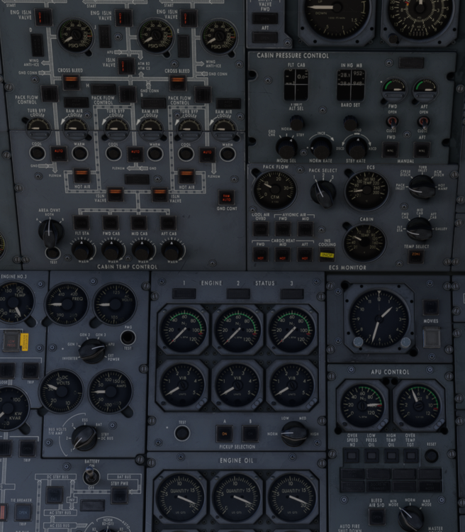
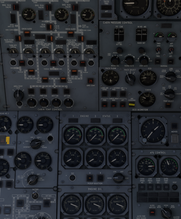
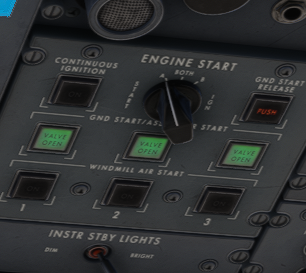
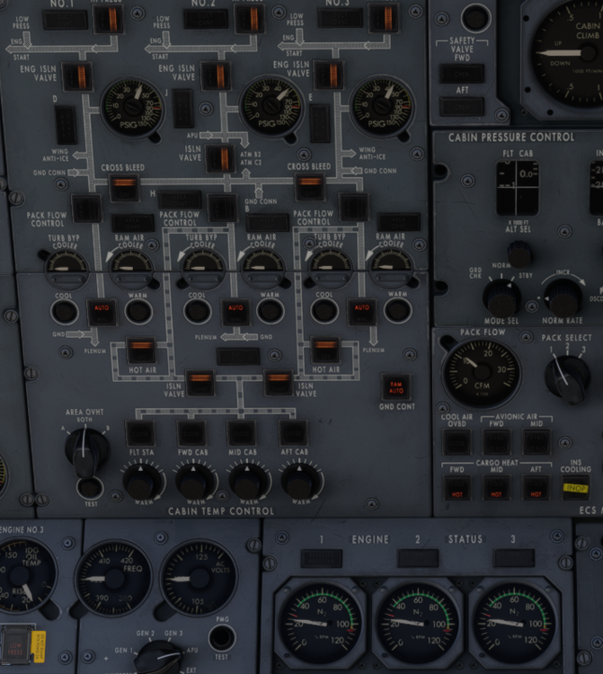
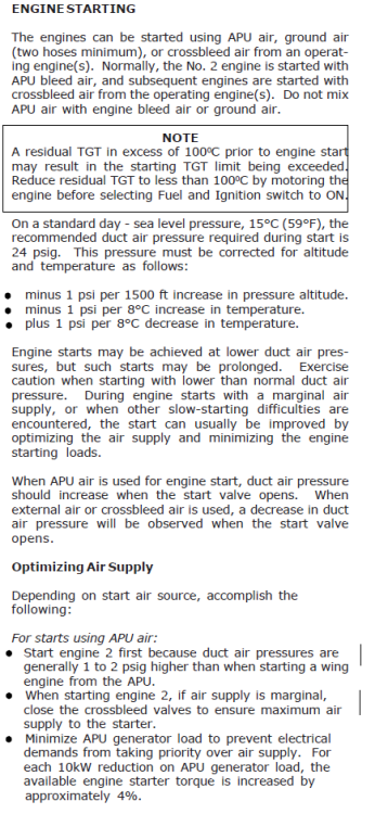
Bleed pressures are showing 50-70 PSIG on APU or engine respectively at idle. Nominal for engine start is 24. Looking at the new pneumatic system sdk, it appears one possible fix may be to modulate the valve position and treat it like an actual load control valve rather than a binary state valve. Additionally the HI PRESS lights do not extinguish at between 73-75% N3.
-
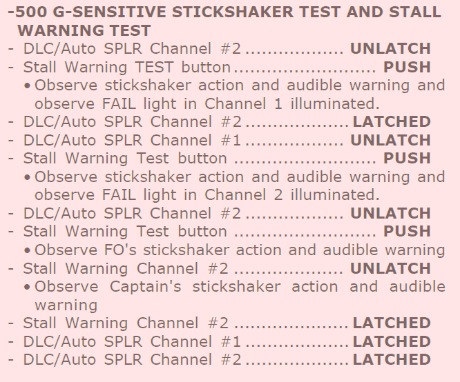
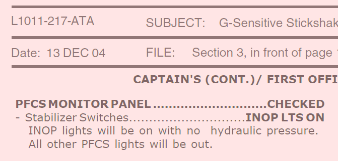
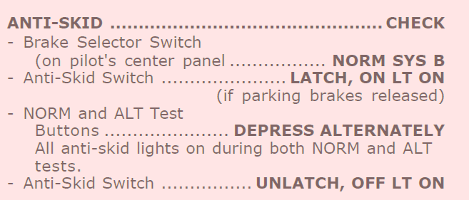
@IniJamir Continuing on with this, some more observations, Stall warning tests are inconsistent with the checklist Missing the audible warning and independent captain / FO shaker activation. The stabilizer PFCS lights should illuminate INOP with no hyd pressure as in the video, they are not INOP. with no hyd pressure. Next The PUSH light should be illuminated if no hyd pressure is available and the rudder limiter switch light is latched.

-
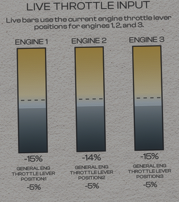
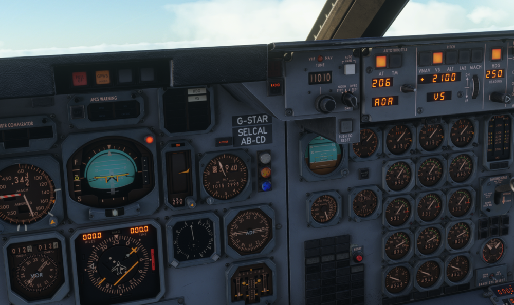
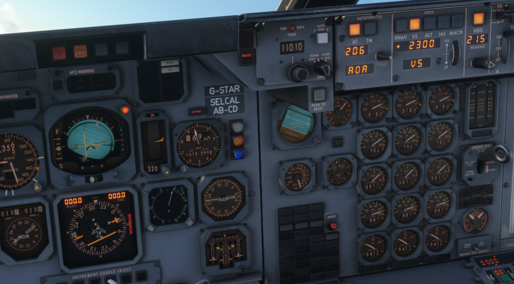
The N1 values on the needle seem to not match the digital readout.

-
IRL AOA is based on the aircraft weight + HSTAB lift. But the HSTAB shouldnt be creating so much lift in the down direction to cause a significant delta AOA. CG primarily affects stability and control-ability.
-
I've found the opposite, I've been fine with every plane except the L1011
-
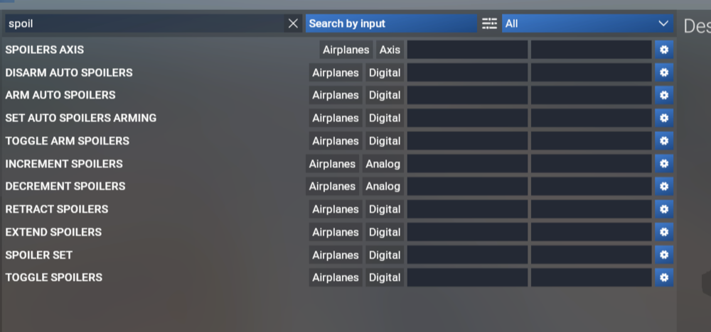
I am having issues with this as well. Im using SPAD, no other bindings for spoilers are present. The alert lights were not illuminated and DLC was functional. After manual deployment


-
While you are reworking the AP-FD modes and logic here is a mode matrix to validate with. Let me know if you need any additional docs. AP-FD_Modes_Matrix.pdf
-
-
-
-
-
-
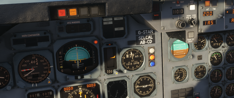
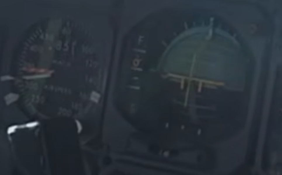
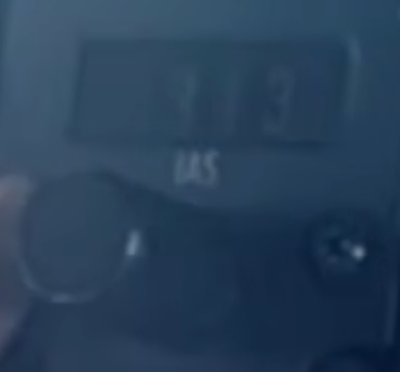
The current speed cue on the FDAI is reversed. The yellow ring indicates the relationship between current speed (yellow ring) and commanded speed (center horizontal line) This can be seen in: Commanded speed is 313 knots with an indicated greater than 313, probably 315 or so based on the speed cue on the FDAI, each wide horizontal line indicates 5 knots. Next The Roll command director will disappear off scale when in heading mode and the commanded roll is maximum It appears the Roll commands a 30° bank angle But a standard rate turn in a transport category aircraft is a maximum command of 25 degrees. Thanks, Mike

-
-
I was looking at the advertising on the store page for the aircraft. I went ahead and pulled the circuit breakers for the INS 1 and INS 2 power, CAPT HSI, and the following and none of those breakers seem to be connected to their associated system or indicator. Is this intended? What is ini was defining as "complete"? Thanks.

-
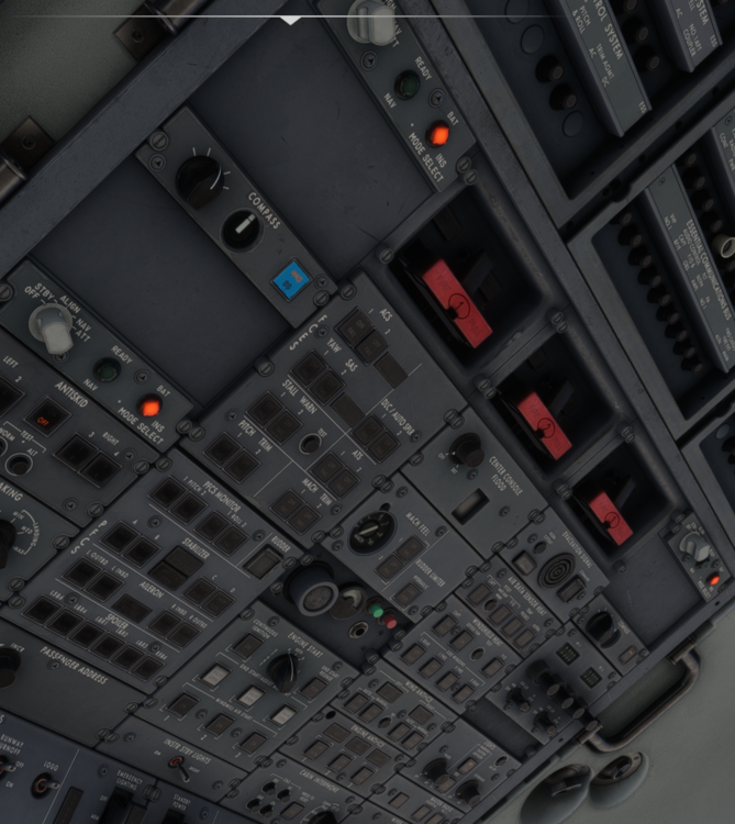
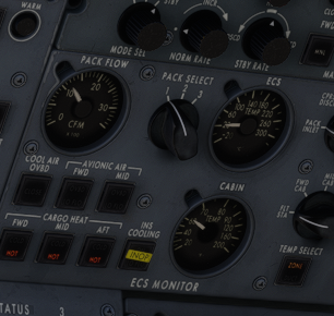
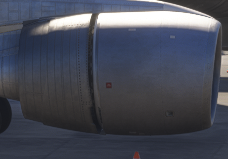
I'm excited for the 1011. I noticed a couple issues not yet mentioned in other threads. When initially powering the aircraft on the INS MSU the BAT annunciator is illuminated. The light is only illuminated when the INS internal batteries are in use powering the INS system. During normal operation this ight would only be triggered by a loss of AC power to the unit. The BAT lights turn off when AC power is applied to the aircraft ECS With APU Bleed Shutoff closed, Pack flow shows 900CFM. With Shutoff open and pack flow control valves open the needle jumps from 1300 cfm to over 3000 cfm Is it intended that the APU is capable of a triple engine start? When the throttles are placed into the idle reverse detent on my system the external model shows the translating cowl only partially deployed. The flight model also seems to indicate that no significant change in thrust has occurred. Would it also be possible to get a list of command variable for SPAD software users? Thanks!