


Agent_Wurst
Member
-
Joined
-
Last visited
-
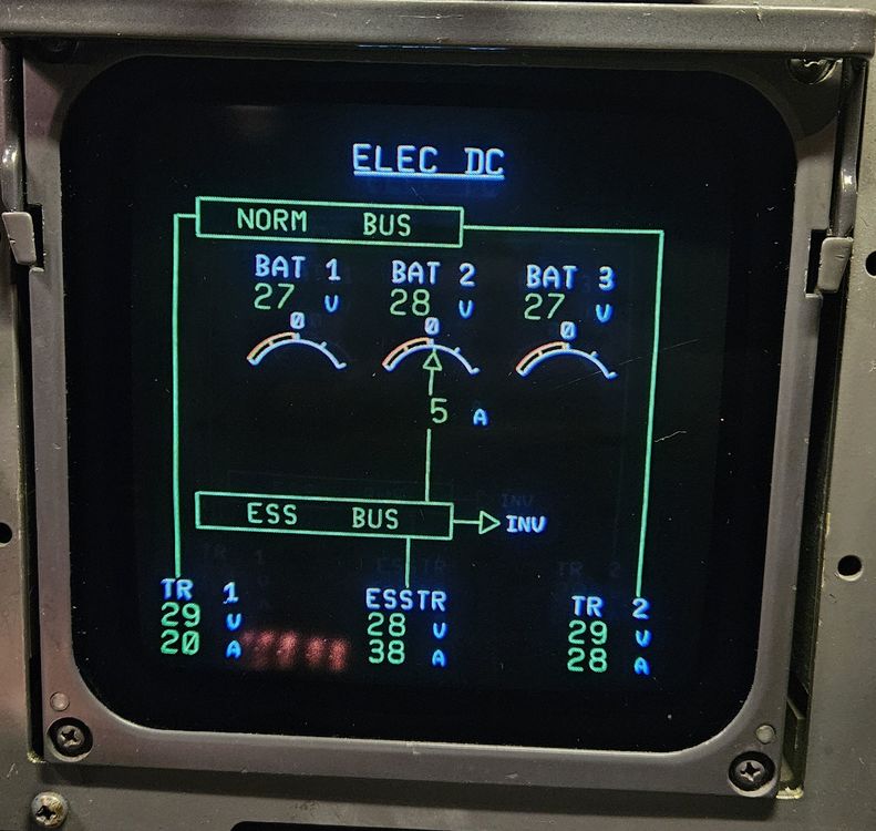
Picture taken from the real aircraft today. I think it depends a bit on the specific aircraft. It's old, maybe the batteries are from different manufacturing dates etc etc. So sometimes even if it's at 28V, it's getting charged, as you can see in the picture. The documentation is not very precise about the charging of the batteries
-
Pictures from today from the real aircraft. Was taken on ground with both engines off
-
I tried it in the MSFS now and it's working correctly for me. The flowbars are indicated until all 3 batteries reach 28V, then the flowbars disappear. When you start the APU, they will come up again.

-
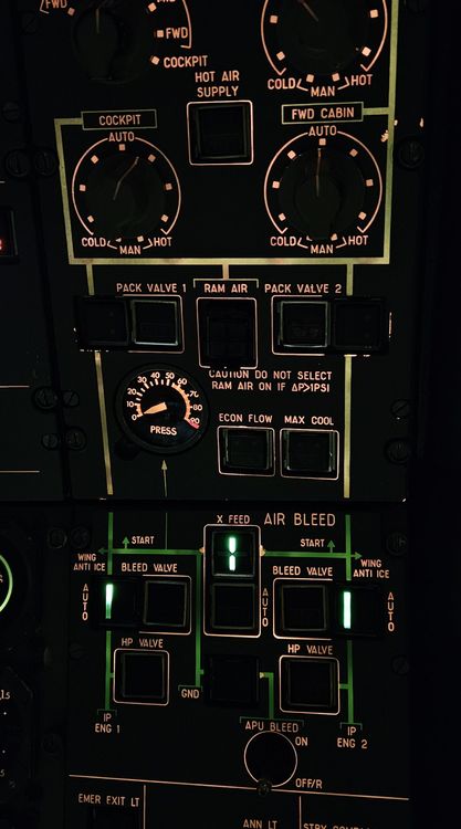
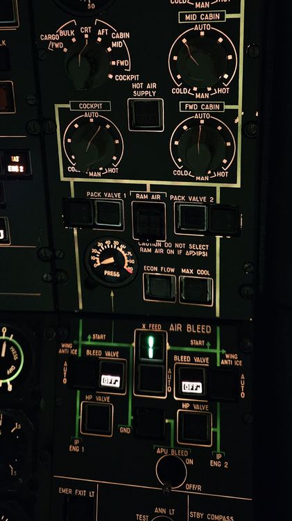
As the previous topic was closed, I will open it here again. In the "real life photo" (from one of the iniBuilds Administrators) of the Air Bleed Overhead Panel, the flowbars were not illuminated. But that was because the brightness of the flow bars was completely turned down. The X-FEED Valve Position flow bar is ALWAYS illuminated, no matter of the conditions met. On Ground with no bleed source, the Bleed Valve Annunciators are also displayed, if the ENG BLEED VALVE pushbuttons are pressed in (ON/Normal Condition)

-
Sorry, I found it 😅 My FCOM 2 says exactly the same with the note "DC BUS TIE is not displayed & DC ESS BUS is amber". But I cannot find a reason for it in the documentation. My assumption is, that with the ELEC PUMPS OFF the STBY GEN has not output, but the DC BUS TIE is still open, so the DC ESS BUS is not fed by the DC NORM BUS for a short period of time
-
In my documentation I can't find anything about the DC ESS BUS Indication being amber
-
Good question. My FCOM says nearly the same as in your screenshot. I'll have a look on my next flight, maybe I can tell you a bit more then 😅
-
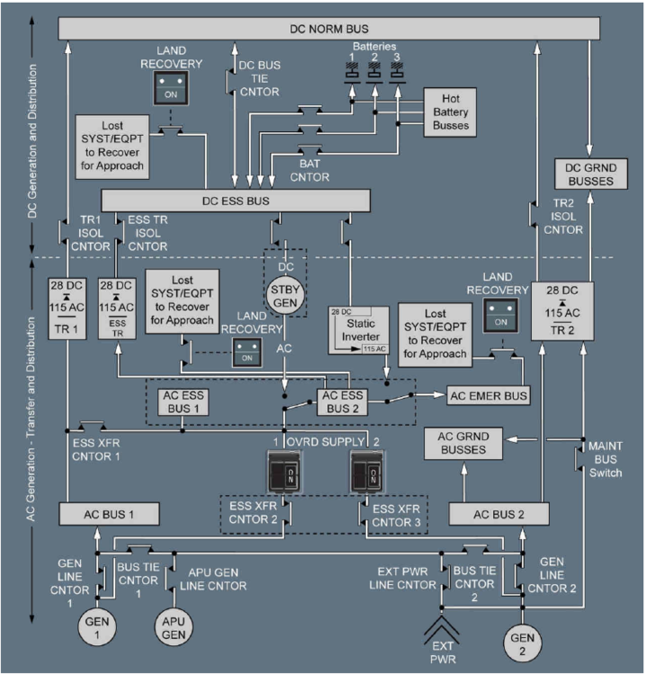
The indication of the ECAM is correct. The Standby Generator supplies the DC ESS BUS, so it's green. Excerpt from FCOM 1: DC ESS BUS POWER SUPPLY The DC ESS BUS is supplied from: ‐ The ESS TR ‐ The DC NORM BUS, through the DC BUS tie contactor which closes as soon as the aircraft network is electrically supplied (except when supplied by EXT PWR). If supply from the DC NORM BUS and ESS TR is lost, the DC ESS BUS is supplied by the standby generator or by the batteries:

-
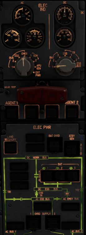
The test won't work with BOTH OVRD SUPPLY Switches ON, because then you are in DUAL OVRD SUPPLY, so everything is split up. The Test should work with only 1 OVRD SUPPLY Switch ON. My company does the test a little different: Only BAT ON (without any OVRD SUPPLY) you check AC EMER ON INV light ON & DC ESS ON BAT light ON. Attached you will find the schematic of the Electrical System
-
During an ILS approach you are in selected speed, so pulling the speed knob has no effect. During a 3D RNP approach, flown in NAV/P.DES, the speed window is blank and you only can select the VAPP in the FMS. But my company has a newer FMS, so I don't know how the 3D RNP works with the old FMS
-
You have to push for a preset. But for the approach we don't use the preset function. In case of go around, we preset the speed to 250kts (or as required) to allow aircraft acceleration by pushing LVL/CH or at ALT* engagement, whichever is first
-
Excerpt from FCOM I: Smoke Detection of Lower Deck Cargo: Applicable to MSN XXX: The cargo compartments smoke detection system comprises 10 smoke detectors: ‐ 2 detectors (LOOP A) plus 2 detectors (LOOP B) installed in the FWD cargo compartment ceiling ‐ 2 detectors (LOOP A) plus 2 detectors (LOOP B) installed in the AFT cargo compartment ceiling ‐ 1 detector (LOOP A) plus 1 detector (LOOP B) installed in the BULK cargo compartment ceiling Applicable to MSN XXX (different than above): The lower deck cargo compartment smoke detection system comprises 6 smoke detectors: ‐ 2 detectors installed in the FWD cargo compartment ceiling ‐ 2 detectors installed in the AFT cargo compartment ceiling ‐ 2 detectors installed in the BULK cargo compartment ceiling. Smoke Detection of Main Deck Cargo: Applicable to MSN XXX: The main deck cargo compartment smoke detection system comprises 24 smoke detectors installed in pairs in cargo compartment floor level and ceiling level: ‐ 8 detectors in MID 1 zone ‐ 8 detectors in MID 2 zone ‐ 8 detectors in AFT zone. At each location, detectors are connected in dual loop. The smoke detection leads to: ‐ The closure of: • Forward and bulk cargo isolation valves • Pack valve 2 if two packs are running • The two main deck isolation valves • Lower deck cargo isolation valves • Hot air supply valve. ‐ The opening of the bypass valve Applicable to MSN XXX (this is of a Production Freighter) The main deck cargo compartment smoke detection system includes: ‐ 4 detectors (LOOP A) plus 4 detectors (LOOP B) installed in the MID 1 cargo compartment ceiling and at floor level behind the DADO panel (2+6) ‐ 4 detectors (LOOP A) plus 4 detectors (LOOP B) installed in the MID 2 cargo compartment ceiling and at floor level behind the DADO panel (2+6) ‐ 4 detectors (LOOP A) plus 4 detectors (LOOP B) installed in the AFT cargo compartment ceiling and at floor level behind the DADO panel (2+6). When smoke is detected on MID 1, MID 2 or AFT cargo, the ventilation is cut off.
-
There are slightly different versions of the A300-600 when it comes to the Cargo Smoke Detection & Fire Extinguishing System and also the window heating. I don't know if it was an option for the airline or just from airbus from on MSN XXX My airline has 24 A300F's and we have 3 different versions of Cargo Smoke Detection systems, depending on the specific aircraft 😅
-
According to the QRH, green dot speed should be 262kt with 127t at FL370. So your indication is correct
-
I can only tell you from my experience that this is a "normal" A300 behavior to a certain extend 😅 Speed drops 2-3kt below the selected VAPP, but then the ATS regains VAPP within 5-10 seconds.


